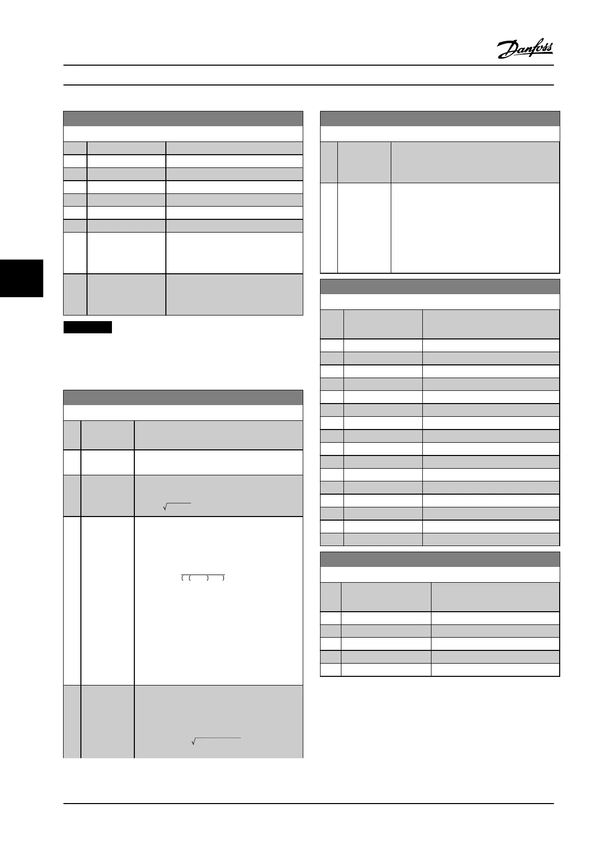
20-00 Feedback 1 Source
Option: Function:
[9] Analog Input X42/1
[10] Analog Input X42/3
[11] Analog Input X42/5
[15] Analog Input X48/2
[100] Bus feedback 1
[101] Bus feedback 2
[102] Bus feedback 3
[104] Sensorless Flow Requires set-up by MCT 10 Set-up
Software with sensorless-specic
plug-in.
[105] Sensorless Pressure Requires set-up by MCT 10 Set-up
Software with sensorless-specic
plug-in.
NOTICE!
If a feedback is not used, set its source to [0] No
Function. Parameter 20-20 Feedback Function determines
how the PID controller uses the three possible feedbacks.
20-01 Feedback 1 Conversion
Option: Function:
This parameter allows a conversion function
to be applied to feedback 1.
[0]
*
Linear No eect on the feedback.
[1] Square root Commonly used when a pressure sensor is
used to provide ow feedback
(( flow ∝ pressure)).
[2] Pressure to
temperature
Used in compressor applications to provide
temperature feedback using a pressure
sensor. The temperature of the refrigerant is
calculated using the following formula:
Temperature =
A2
ln Pe + 1 − A1
− A3,
where A1, A2 and A3 are refrigerant-specic
constants. Select the refrigerant in
parameter 20-30 Refrigerant.
Parameter 20-21 Setpoint 1 through
parameter 20-23 Setpoint 3 allow the values of
A1, A2 and A3 to be entered for a refrigerant
that is not listed in
parameter 20-30 Refrigerant.
[3] Pressure to
ow
Used in applications for controlling the air
ow in a duct. A dynamic pressure
measurement (pitot tube) represents the
feedback signal.
Flow = DuctArea × DynamicPressure
× AirDensityFactor
20-01 Feedback 1 Conversion
Option: Function:
See also parameter 20-34 Duct 1 Area [m2]
through parameter 20-38 Air Density Factor [%]
for setting of duct area and air density.
[4] Velocity to
ow
Used in applications for controlling the air
ow in a duct. An air velocity measurement
represents the feedback signal.
Flow = DuctArea × AirVelocity
See also parameter 20-34 Duct 1 Area [m2]
through parameter 20-37 Duct 2 Area [in2] for
setting of duct area.
20-03 Feedback 2 Source
Option: Function:
See parameter 20-00 Feedback 1
Source for details.
[0] * No function
[1] Analog Input 53
[2] Analog Input 54
[3] Pulse input 29
[4] Pulse input 33
[7] Analog input X30/11
[8] Analog input X30/12
[9] Analog Input X42/1
[10] Analog Input X42/3
[11] Analog Input X42/5
[15] Analog Input X48/2
[100] Bus feedback 1
[101] Bus feedback 2
[102] Bus feedback 3
[104] Sensorless Flow
[105] Sensorless Pressure
20-04 Feedback 2 Conversion
Option: Function:
See parameter 20-01 Feedback 1
Conversion for details.
[0] * Linear
[1] Square root
[2] Pressure to temperature
[3] Pressure to ow
[4] Velocity to ow
How to Program
VLT
®
HVAC Drive FC 102
100 Danfoss A/S © 08/2014 All rights reserved. MG11F522
66
 Loading...


