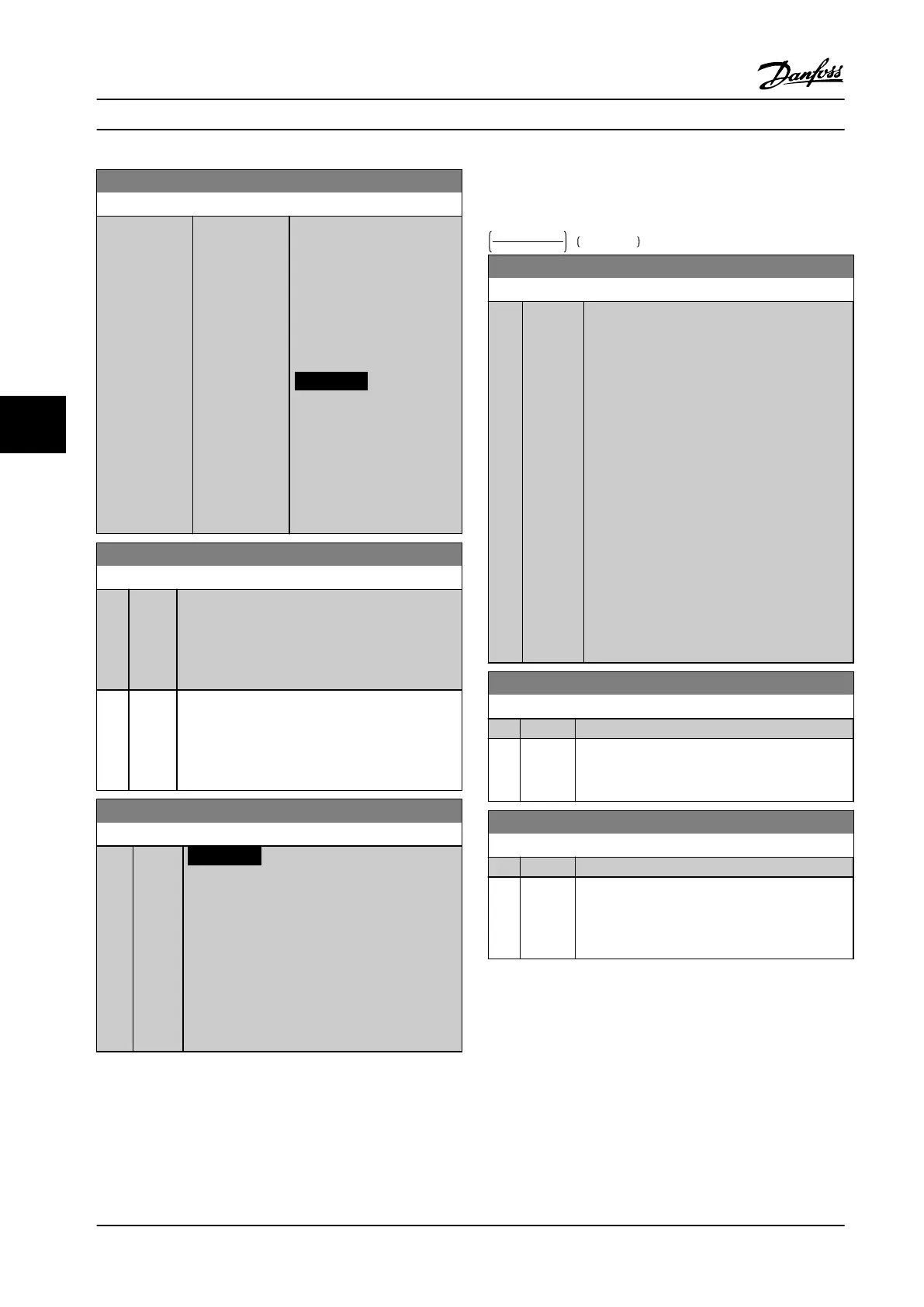
20-22 Setpoint 2
Range: Function:
0
ProcessCtrlUnit*
[-999999.999 -
999999.999
ProcessCtrlUnit]
Setpoint 2 is used in closed-
loop mode to enter a setpoint
reference that may be used
by the adjustable frequency
drive’s PID controller. See the
description of
parameter 20-20 Feedback
Function.
NOTICE!
The setpoint reference
entered here is added to
any other references that
are enabled (see
parameter group 3-1*
References).
20-81 PID Normal/ Inverse Control
Option: Function:
[0] * Normal The adjustable frequency drive’s output frequency
decreases when the feedback is greater than the
setpoint reference. This behavior is common for
pressure-controlled supply fan and pump
applications.
[1] Inverse The adjustable frequency drive’s output frequency
increases when the feedback is greater than the
setpoint reference. This behavior is common for
temperature-controlled cooling applications, such
as cooling towers.
20-93 PID Proportional Gain
Range: Function:
0.50* [0 -
10 ]
NOTICE!
Always set the desired value for
parameter 20-14 Maximum Reference/Feedb.
before setting the values for the PID
Controller in parameter group 20-9* PID
Controller.
The proportional gain indicates the number of
times the error between the setpoint and the
feedback signal is to be applied.
If (Error x Gain) jumps with a value equal to what is set in
parameter 20-14 Maximum Reference/Feedb., the PID
controller tries to change the output speed equal to what
is set in parameter 4-13 Motor Speed High Limit [RPM]/
parameter 4-14 Motor Speed High Limit [Hz]. However, the
output speed is limited by this setting.
The proportional band (error causing output to change
from 0–100%) can be calculated with the formula:
1
ProportionalGain
× MaxReference
20-94 PID Integral Time
Range: Function:
20
s*
[0.01 -
10000 s]
The integrator accumulates a contribution to
the output from the PID controller as long as
there is a deviation between the reference/
setpoint and feedback signals. The contribution
is proportional to the size of the deviation. This
ensures that the deviation (error) approaches
zero.
Quick response on any deviation is obtained
when the integral time is set to a low value.
Setting it too low, however, may cause the
control to become unstable.
The value set is the time needed for the
integrator to add the same contribution as the
proportional for a certain deviation.
If the value is set to 10000, the controller acts
as a pure proportional controller with a P-band
based on the value set in parameter 20-93 PID
Proportional Gain. When no deviation is present,
the output from the proportional controller is 0.
22-21 Low Power Detection
Option: Function:
[0] * Disabled
[1] Enabled Carry out the low-power detection commissioning
to set the parameters in parameter group 22-3*
No-Flow Power Tuning for proper operation.
22-22 Low Speed Detection
Option: Function:
[0] * Disabled
[1] Enabled Detects when the motor operates with a speed
as set in parameter 4-11 Motor Speed Low Limit
[RPM] or parameter 4-12 Motor Speed Low Limit
[Hz].
How to Program
VLT
®
HVAC Drive FC 102
104 Danfoss A/S © 08/2014 All rights reserved. MG11F522
66
 Loading...


