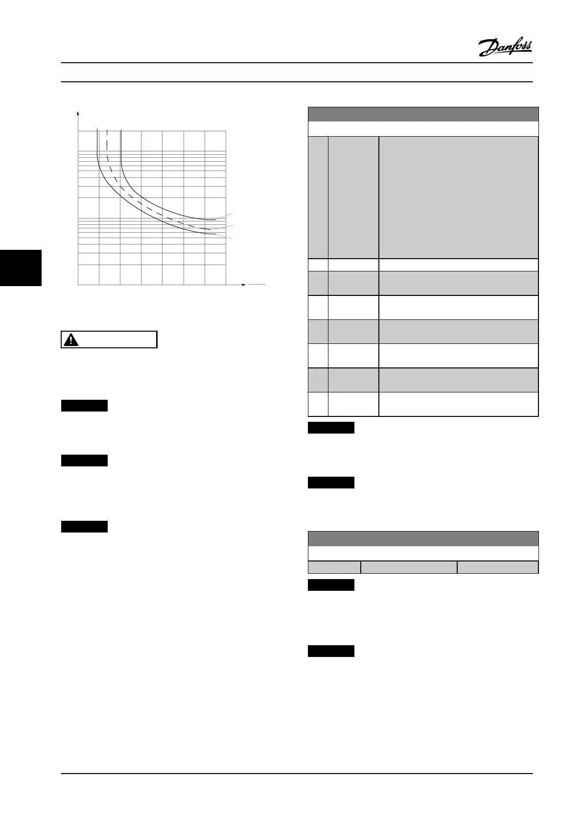
1.21.0 1.4
30
10
20
100
60
40
50
1.81.6 2.0
2000
500
200
400
300
1000
600
t [s]
175ZA052.11
fOUT = 0.2 x f M,N
fOUT = 2 x f M,N
fOUT = 1 x f M,N
IMN
IM
Figure 6.9
WARNING
In order to maintain PELV, all connections made to the
control terminals must be PELV, e.g., thermistor must be
reinforced/double-insulated.
NOTICE!
Danfoss recommends using 24 V DC as thermistor supply
voltage.
NOTICE!
The ETR timer function does not work when
parameter 1-10 Motor Construction = [1] PM, non-salient
SPM.
NOTICE!
For correct operation of ETR function, setting in
parameter 1-03 Torque Characteristics must t the
application (see description of parameter 1-03 Torque
Characteristics).
1-93 Thermistor Source
Option: Function:
Select the input to which the thermistor (PTC
sensor) should be connected. An analog
input option [1] or [2] cannot be selected if
the analog input is already in use as a
reference source (selected in
parameter 3-15 Reference 1 Source,
parameter 3-16 Reference 2 Source or
parameter 3-17 Reference 3 Source ).
When using MCB 112, choice [0] None must
always be selected.
[0] * None
[1] Analog Input
53
[2] Analog Input
54
[3] Digital input
18
[4] Digital input
19
[5] Digital input
32
[6] Digital input
33
NOTICE!
This parameter cannot be adjusted while the motor is
running.
NOTICE!
Digital input should be set to [0] PNP - Active at 24 V in
parameter 5-00 Digital I/O Mode.
2-00 DC Hold/Preheat Current
Range: Function:
50 %* [ 0 - 160 %]
NOTICE!
Parameter 2-00 DC Hold/Preheat Current will not have
eect when parameter 1-10 Motor Construction = [1] PM,
non-salient SPM.
NOTICE!
The maximum value depends on the rated motor
current.
Avoid 100% current for too long. It may damage the
motor.
How to Program
VLT
®
HVAC Drive FC 102
90 Danfoss A/S © 08/2014 All rights reserved. MG11F522
66
 Loading...


