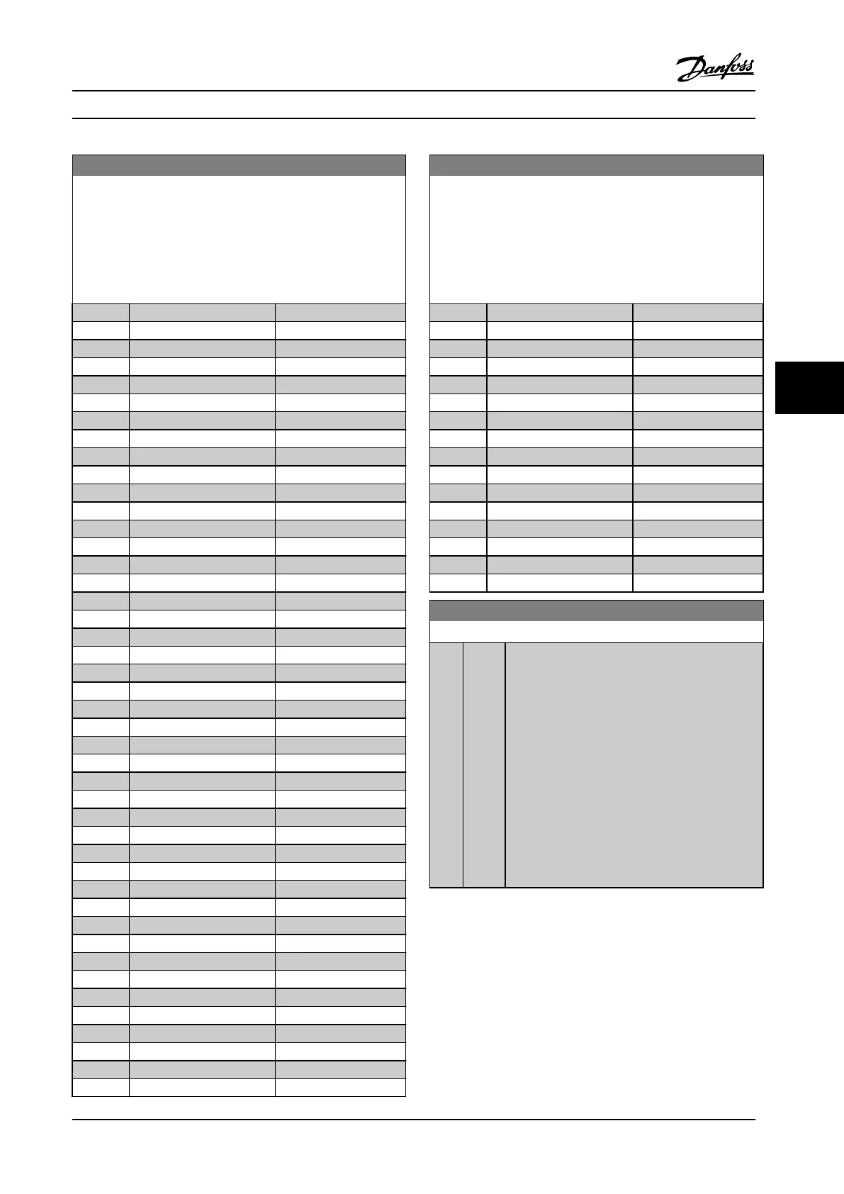
5-40 Function Relay
Array [8]
(Relay 1 [0], Relay 2 [1]
Option MCB 105: Relay 7 [6], Relay 8 [7] and Relay 9 [8]).
Select options to dene the function of the relays.
The selection of each mechanical relay is realized in an array
parameter.
Option: Function:
[19] Below feedback, low
[20] Above feedback, high
[21] Thermal warning
[25] Reverse
[26] Bus OK
[27] Torque limit stop
[28] Brake: No Brake War
[29] Brake ready, no fault
[30] Brake fault (IGBT)
[33] Safe stop active
[35] External Interlock
[36] Control word bit 11
[37] Control word bit 12
[40] Out of ref range
[41] Below reference, low
[42] Above ref, high
[45] Bus ctrl.
[46] Bus ctrl, 1 if timeout
[47] Bus ctrl, 0 if timeout
[60] Comparator 0
[61] Comparator 1
[62] Comparator 2
[63] Comparator 3
[64] Comparator 4
[65] Comparator 5
[70] Logic rule 0
[71] Logic rule 1
[72] Logic rule 2
[73] Logic rule 3
[74] Logic rule 4
[75] Logic rule 5
[80] SL digital output A
[81] SL digital output B
[82] SL digital output C
[83] SL digital output D
[84] SL digital output E
[85] SL digital output F
[160] No alarm
[161] Running reverse
[165] Local ref active
[166] Remote ref active
[167] Start command activ
[168] Hand/O
[169] Auto mode
5-40 Function Relay
Array [8]
(Relay 1 [0], Relay 2 [1]
Option MCB 105: Relay 7 [6], Relay 8 [7] and Relay 9 [8]).
Select options to dene the function of the relays.
The selection of each mechanical relay is realized in an array
parameter.
Option: Function:
[180] Clock Fault
[181] Prev. Maintenance
[188] AHF Capacitor Connect
[189] External Fan Control
[190] No-Flow
[191] Dry Pump
[192] End Of Curve
[193] Sleep Mode
[194] Broken Belt
[195] Bypass Valve Control
[196] Fire Mode
[197] Fire Mode was Act.
[198] Drive Bypass
[211] Cascade Pump 1
[212] Cascade Pump 2
[213] Cascade Pump 3
6-00 Live Zero Timeout Time
Range: Function:
10 s* [1 -
99 s]
Enter the Live Zero Time-out time period. Live
Zero Time-out Time is active for analog inputs, i.e.
terminal 53 or terminal 54, used as reference or
feedback sources. If the reference signal value
associated with the selected current input falls
below 50% of the value set in
parameter 6-10 Terminal 53 Low Voltage,
parameter 6-12 Terminal 53 Low Current,
parameter 6-20 Terminal 54 Low Voltage or
parameter 6-22 Terminal 54 Low Current for a time
period longer than the time set in
parameter 6-00 Live Zero Timeout Time, the
function selected in parameter 6-01 Live Zero
Timeout Function will be activated.
How to Program Instruction Manual
MG11F522 Danfoss A/S © 08/2014 All rights reserved. 95
6 6
 Loading...


