NOTICE
The plinth is provided in the same packaging as the frequency converter but is not attached to enclosure types F1-F4
during shipment. The plinth is required to allow airflow to the frequency converter to provide proper cooling. The F
enclosures should be positioned on top of the plinth in the final installation location. The angle from the top of the
frequency converter to the lifting cable should be 60° or greater.
In addition to the drawings above, a spreader bar is an acceptable way to lift the F enclosures.
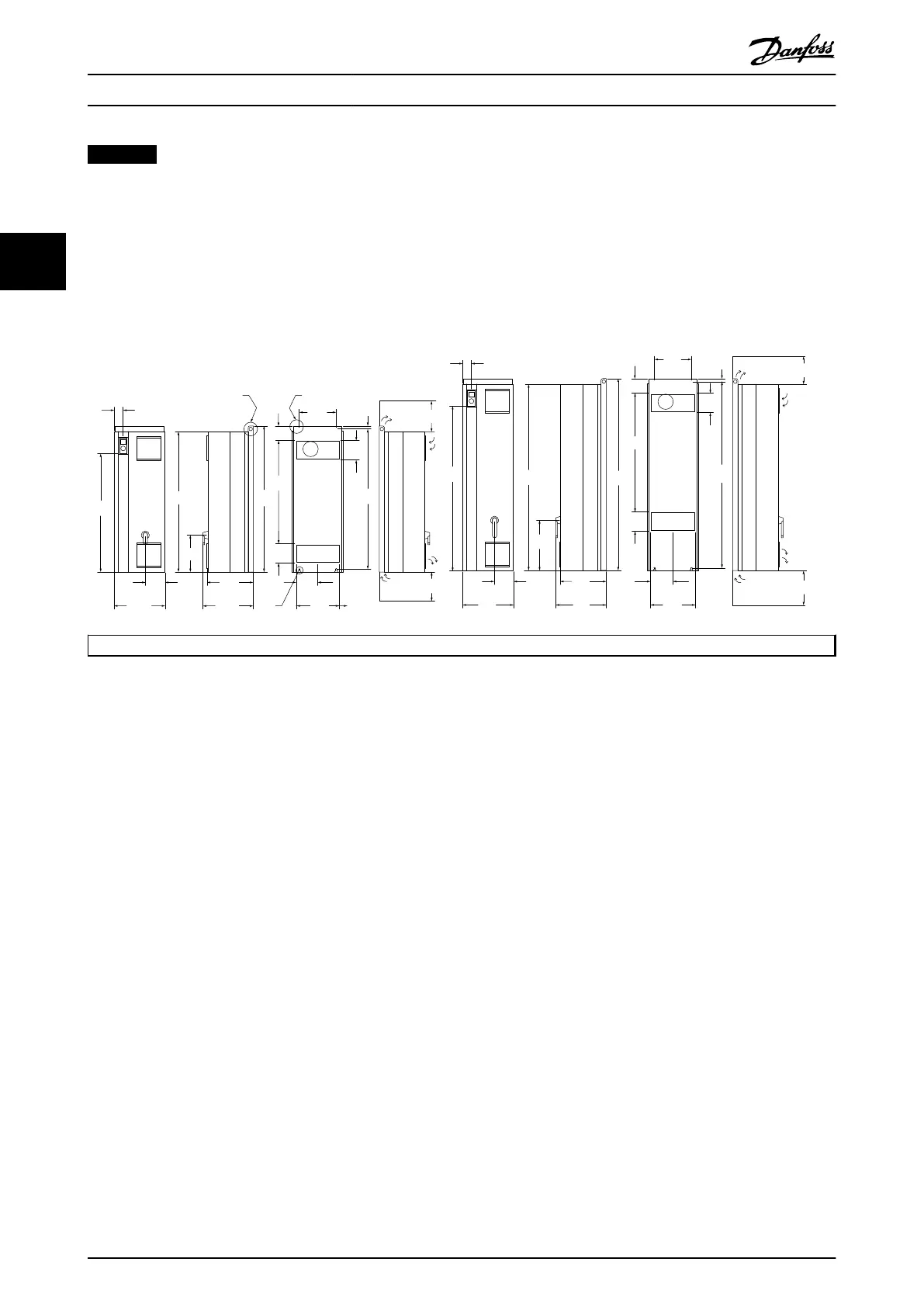
3.2.5 Mechanical Dimensions
IP21 AND IP54 / UL AND NEMA TYPE 1 AND 12
A
B
C
120
(4.7)
177.0
(7.0)
354.0
(13.9)
1166
(45.9)
310
(12.2)
163
(6.4)
420
(16.5)
981
(38.6)
74
(2.9)
417
(16.4)
380
(15.0)
D1
D2
130BA443.11
417
(16.4)
380
(15.0)
225
(8.9)
225
(8.9)
225.0
(8.9)
225.0
(8.9)
369.0
(14.5)
849
(33.4)
1209
(47.6)
160.0
(6.3)
160.0
(6.3)
160.0
(6.3)
160.0
(6.3)
304
(12.0)
304
(12.0)
25
(1.0)
25
(1.0)
1154
(45.4)
1362
(53.6)
420
(16.5)
157
(6.2)
72
(2.8)
1547
(60.9)
1589
(62.6)
423
(16.6)
120
(4.7)
1535
(60.4)
184.5
(7.3)
977
(38.5)
*
Note airflow directions
Illustration 3.10
Mechanical Installation VLT HVAC Drive FC 102 Operating Instructions
12 MG11F402 - Rev. 2013-12-16
33
 Loading...


