APPLICATION GUIDELINES
FRCC.PC.007.B5.02
21
ELECTRICAL DATA, CONNECTIONS AND WIRING
Motor protection
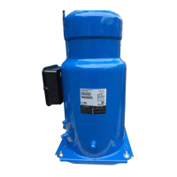
Compressor models SH090-105-120-140-161
-184 have been provided with an internal over-
load motor protection to prevent against exces-
sive current and temperature caused by overload-
ing, low refrigerant fl ow or phase loss. The cutout
current is the MCC value listed in section "Three
phase electrical characteristics".
The protector is located in the star point of the
motor and, should it be activated, will cut out all
three phases. It will be reset automatically.
While not compulsory, an additional external
overload is still advisable for either alarm or man-
ual reset.
Then it must be set below MCC value (at max op-
erating current:
when the motor temperature is too high, •
then the internal protector will trip
when the current is too high the external •
overload protection will trip before the in-
ternal protection therefore off ering possibil-
ity of manual reset.
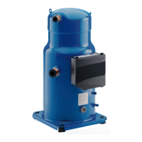
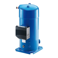
Compressor models SH180-240-300-380 are
delivered with a pre installed motor protection
module inside the terminal box. This device pro-
vides for effi cient and reliable protection against
overheating and overloading (as well as phase
loss/reversal on SH240-300-380).
The motor protector comprises a control module
and PTC sensors embedded in the motor winding.
The close contact between thermistors and wind-
ings ensures a very low level of thermal inertia.
The motor temperature is being constantly
measured by a PTC thermistor loop connected
on S1-S2 (called 1-2 on SH180). If any thermistor
exceeds its response temperature, its resistance
increases above the trip level (4,500 Ω) and the
output relay then trips – i.e. contacts M1-M2 (or
11-14 for SH180) are open. After cooling to below
the response temperature (resistance < 2,750 Ω),
a 5-minute time delay is activated. After this delay
has elapsed, the relay is once again pulled in – i.e.
contacts M1-M2 (11-14 for SH180) are closed. The
time delay may be cancelled by means of reset-
ting the mains (L-N -disconnect) for approximate-
ly 5 sec.
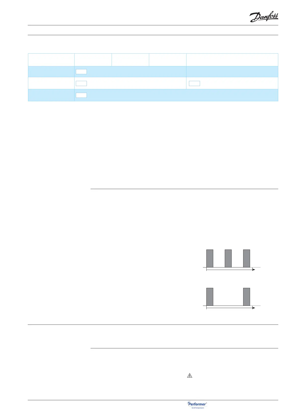
When present, the LED on module will lighten as
follows in case of overheat:
PTC overheat
Appr. 1 second
Delay timer active (after PTC over temp.)
Appr. 1 second
Use a phase meter to establish the phase orders
and connect line phases L1, L2 and L3 to terminals
T1, T2 and T3, respectively. The compressor will
only operate properly in a single direction, and
the motor is wound so that if the connections are
correct, the rotation will also be correct.
Phase sequence and
reverse rotation protection
Compressor models SH090-105-120-140-161-
184 have no internal reverse rotation protection.
If reverse rotation occurs it will be obvious as
soon as power is turned on. The compressor will
not build-up any pressure, the sound level will be
abnormally high and power consumption will be
minimal. In such case, shut down the compres-
sor immediately and connect the phases to their
proper terminals. Prolonged reverse rotation will
damage the compressor.
Phase sequence detector is strongly
recommended.
9
Compressor model
Overheating
protection
Over current
protection
Locked rotor
protection
Phase reversal protection
SH 090 - 105 - 120 - 140-
161 - 184
Internal motor protection Phase sequence detector recommended
SH 180 Electronic module located in terminal box Reverse vent valve
SH240 - 300 - 380 Electronic module located in terminal box
9
9
9
 Loading...