APPLICATION GUIDELINES
4
FRCC.PC.007.B5.02
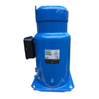
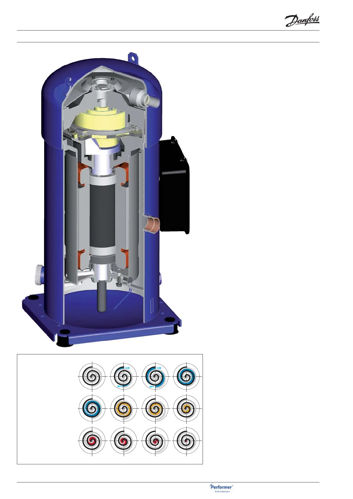
In a Performer® SH scroll compressor, the com-
pression is performed by two scroll elements lo-
cated in the upper part of the compressor.
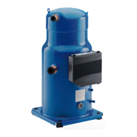
Suction gas enters the compressor at the suc-
tion connection. As all of the gas fl ows around
and through the electrical motor, thus ensuring
complete motor cooling in all applications, oil
droplets separate and fall into the oil sump. After
exiting the electrical motor, the gas enters the
scroll elements where compression takes place.
Ultimately, the discharge gas leaves the compres-
sor at the discharge connection.
The fi gure below illustrates the entire compres-
sion process. The centre of the orbiting scroll (in
grey) traces a circular path around the centre of
the fi xed scroll (in black). This movement creates
symmetrical compression pockets between the
two scroll elements. Low-pressure suction gas is
trapped within each crescent-shaped pocket as it
gets formed; continuous motion of the orbiting
scroll serves to seal the pocket, which decreases
in volume as the pocket moves towards the cen-
tre of the scroll set increasing the gas pressure.
Maximum compression is achieved once a pocket
reaches the centre where the discharge port is
located; this stage occurs after three complete
orbits. Compression is a continuous process: the
scroll movement is suction, compression and dis-
charge all at the same time.
SCROLL COMPRESSION PRINCIPLE
SUCTION
COMPRESSION
DISCHARGE