APPLICATION GUIDELINES
26
FRCC.PC.007.B5.02
OPERATING CONDITIONS
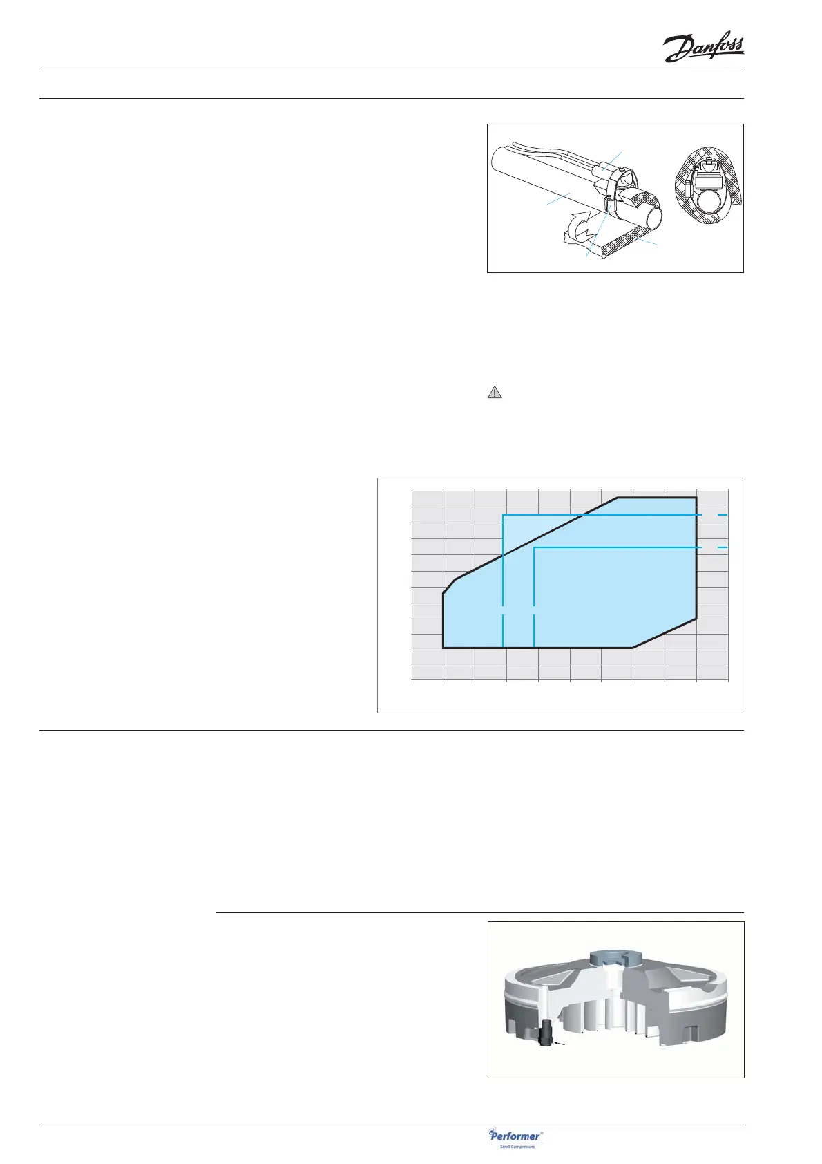
DGT protection is required if the high and low
pressure switch settings do not protect the com-
pressor against operations beyond its specifi c ap-
plication envelope. Please refer to the examples
below, which illustrate where DGT protection is
required (Ex.1) and where it is not (Ex.2).
A discharge gas temperature protection device
must be installed on all heat pumps. In revers-
ible air-to-air and air-to-water heat pumps the
discharge temperature must be monitored
during development test by the equipment
manufacturer.
The DGT should be set to open at a discharge gas
temperature of 135°C.
The compressor must not be allowed to cycle
on the discharge gas thermostat. Continuous op-
erations beyond the compressor’s operating range
will cause serious damage to the compressor!
A high-pressure (HP) safety switch is required to
shut down the compressor should the discharge
pressure exceed the values shown in the table
section "System pressure test". The high-pressure
switch can be set to lower values depending on
the application and ambient conditions. The HP
switch must either be placed in a lockout circuit
or consist of a manual reset device to prevent cy-
cling around the high-pressure limit. If a discharge
valve is used, the HP switch must be connected to
the service valve gauge port, which must not be
isolated.
High and low
pressure protection
The SH380 incorporate an internal relief valve set
to open between the internal high and low pres-
sure sides of the compressor when the pressure
diff erential between the discharge and suction
pressures surpasses 31 to 38 bar.
This safety feature prevents the compressor from
developing dangerously high pressures should
the high pressure cut-out, for whatever reason,
fail to shut down the compressor.
Internal pressure relief valve
High pressure
The discharge gas temperature must not exceed
135°C.
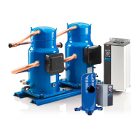
The discharge gas thermostat accessory kit (code
7750009) includes all components required for in-
stallation as shown below. The thermostat must
be attached to the discharge line within 150 mm
from the compressor discharge port and must be
thermally insulated and tightly fi xed on the pipe.
Discharge temperature
protection
70
65
60
55
50
45
40
35
30
25
20
15
10
-30 -25 -20 -15
-10
-5 0 5 10 15 20
Cond. temp. (°C)
Evap. temp. (°C)
LP1
HP2
HP1
R410A
DGT - limit
Example 1
Example 2
LP2
Example 1 (R410A, SH = 11 K)
LP switch setting:
LP1 = 3.3 bar (g) (-15.5°C)
HP switch setting:
HP1 = 38 bar (g) (62°C)
Risk of operation beyond the applica-
tion envelope.
DGT protection required.
Example 2 (R410A, SH = 11 K)
LP switch setting:
LP2 = 4.6 bar (g) (-10.5°C)
HP switch setting:
HP2 = 31 bar (g) (52°C)
No risk of operation beyond the ap-
plication envelope.
No DGT protection required.
Discharge line
Insulation
Bracket
Thermostat
HP
LP
Relief valve