Page 20 of 108
M-AP-001-EN Rev. N
M-AP-001-EN Rev. N
Functional Description
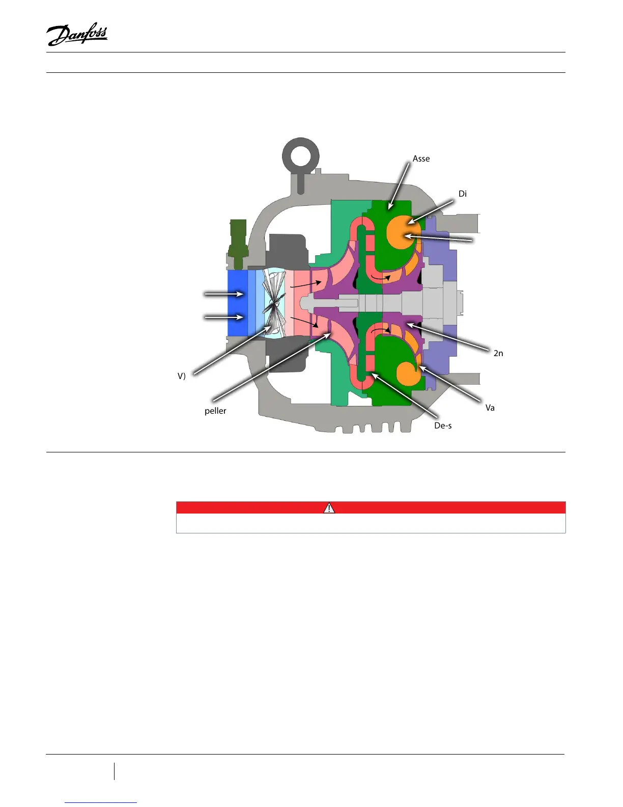
Figure 3-2 - Compressor
Fluid Path (TG310, TT350,
TG390, TT400, TG520, and
TT700)
3.2 Motor Cooling Liquid refrigerant is channelled at full condenser pressure from the main liquid line to the
compressor to cool the electronic, mechanical, and electromechanical components (see
Figure 3-3 and Figure 3-4).
The sub-cooled refrigerant enters the compressor through two solenoid valves and
associated xed orices located behind the service access cover. The orices cause the
refrigerant to expand, thereby lowering its temperature. Both valves operate relative to the
temperature at the sensors that are located at the Insulated Gate Bipolar Transistor (IGBT)
Inverter and motor cavity. When the temperature at either sensor reaches a pre-determined
threshold, one solenoid valve opens. If the temperature increases to the point where it
equals a higher temperature threshold, the second solenoid valve opens.
From the outlet of the orices, the refrigerant is directed to the heatsink plate of the inverter
and then to the underside of the SCR heatsink. From there, the refrigerant passes through
grooves surrounding the motor stator. As the refrigerant ows through the grooves, it
vaporizes into a gas. At the coil outlet, the refrigerant gas is channeled back to the suction
inlet via the motor cavity, thereby cooling the rotor. All models with the exception of the
TT300 and TG230 use a split-cooling method where the motor and electronics portions are
cooled separately by refrigerant liquid.
• • • CAUTION • • •
A minimum operating pressure ratio of 1.5 is required to maintain adequate cooling of the compressor.
Inlet Guide Vanes (IGV)
1st Stage Impeller
De-swirl Vanes
Vaneless Diffuser
2nd Stage Impeller
Discharge Port
Volute
Assembly
Low - Pressure / Low -
Temperature Gas
High - Pressure /
High - Temperature
Gas
 Loading...
