Page 38 of 108
M-AP-001-EN Rev. N
M-AP-001-EN Rev. N
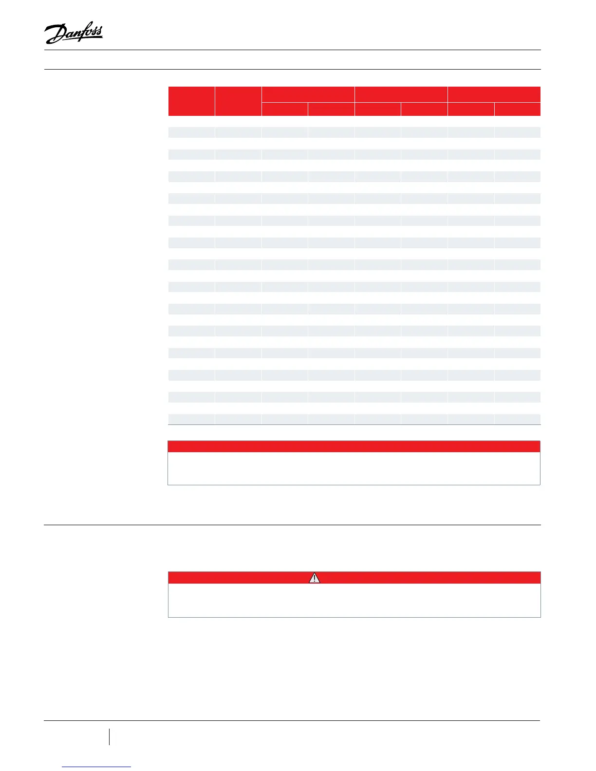
Table 6-3 - FLA and LRA
Value Range
Model Voltage
FLA LRA Default
Min Max* Min Max FLA LRA
TG230 380V 40 106 44 117 40 44
TG230 400V 40 106 44 117 40 44
TG230 460V 40 99 44 110 40 44
TG230 575V 40 79 44 88 40 44
TG310 380V 50 150 55 165 50 55
TG310 400V 50 150 55 165 50 55
TG310 460V 50 135 55 145 50 55
TG390 380V 50 123 55 137 50 55
TG390 400V 50 123 55 137 50 55
TG390 460V 50 108 55 120 50 55
TG390 575V 50 86 55 96 50 55
TG520 380V 50 149 55 165 50 55
TG520 400V 50 142 55 158 50 55
TG520 460V 50 123 55 137 50 55
TT300 380V 40 145 44 160 40 44
TT300 400V 40 145 44 160 40 44
TT300 460V 40 135 44 150 40 44
TT300 575V 40 110 44 121 40 44
TT350 380V 50 210 55 231 50 55
TT350 400V 50 210 55 231 50 55
TT350 460V 50 180 55 198 50 55
TT400 380V 60 170 66 187 60 66
TT400 400V 60 170 66 187 60 66
TT400 460V 60 150 66 165 60 66
TT400 575V 60 120 66 132 60 66
TT700 380V 60 206 66 227 60 66
TT700 400V 60 196 66 216 60 66
TT700 460V 60 170 66 187 60 66
Electrical Specications
An input disconnect (for example, a switch or circuit breaker) must be installed in the line
before the compressor in accordance with applicable local, national, and international codes
(for example, NEC/CEC). Size the disconnect according to the full-load current.
Refer to Figure 20-9 for interconnection details.
6.3 Disconnects
• • • CAUTION • • •
The full-load current rating is based on the installation of a line reactor in the power line. Refer to the Spare Parts Selection Guide
for specications. Failure to use a line reactor will result in poor power factor and higher full-load current.
NOTE
Refer to the OEM Programming Guide to identify specic registers associated with the “3-Phase Over Current Alarm (FLA) and
3-Phase Over Current Fault (LRA).”
 Loading...
