Page 99 of 108
M-AP-001-EN Rev. N
Installation
20.6.3 Voltage-Free
Contacts
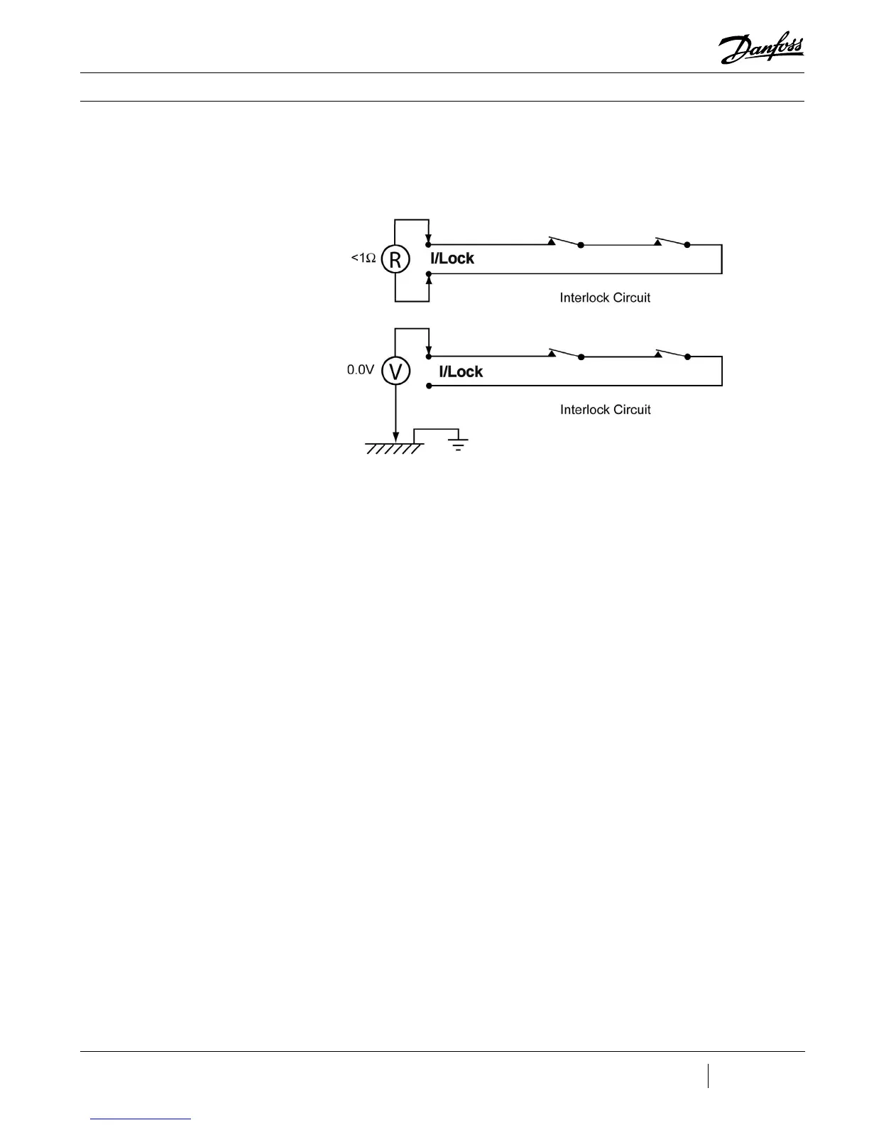
Prior to connecting the interlock terminals of the compressor I/O board, measure the
resistance across the customer’s interlock terminals (see Figure 20-8). Ensure that the
interlock contacts are closed. The measured value should be less than 1Ω.
Figure 20-8 - Interlock Circuit
Tests
Measure the voltage between each customer interlock terminal and the frame ground while
the interlock contacts are open and closed. In either contact state, if the measured voltage
is not zero, verify the source of the voltage. Do not connect the interlock terminals until the
voltage source is removed (see Figure 20-9).
 Loading...
