Page 60 of 108
M-AP-001-EN Rev. N
M-AP-001-EN Rev. N
System Design Guidelines
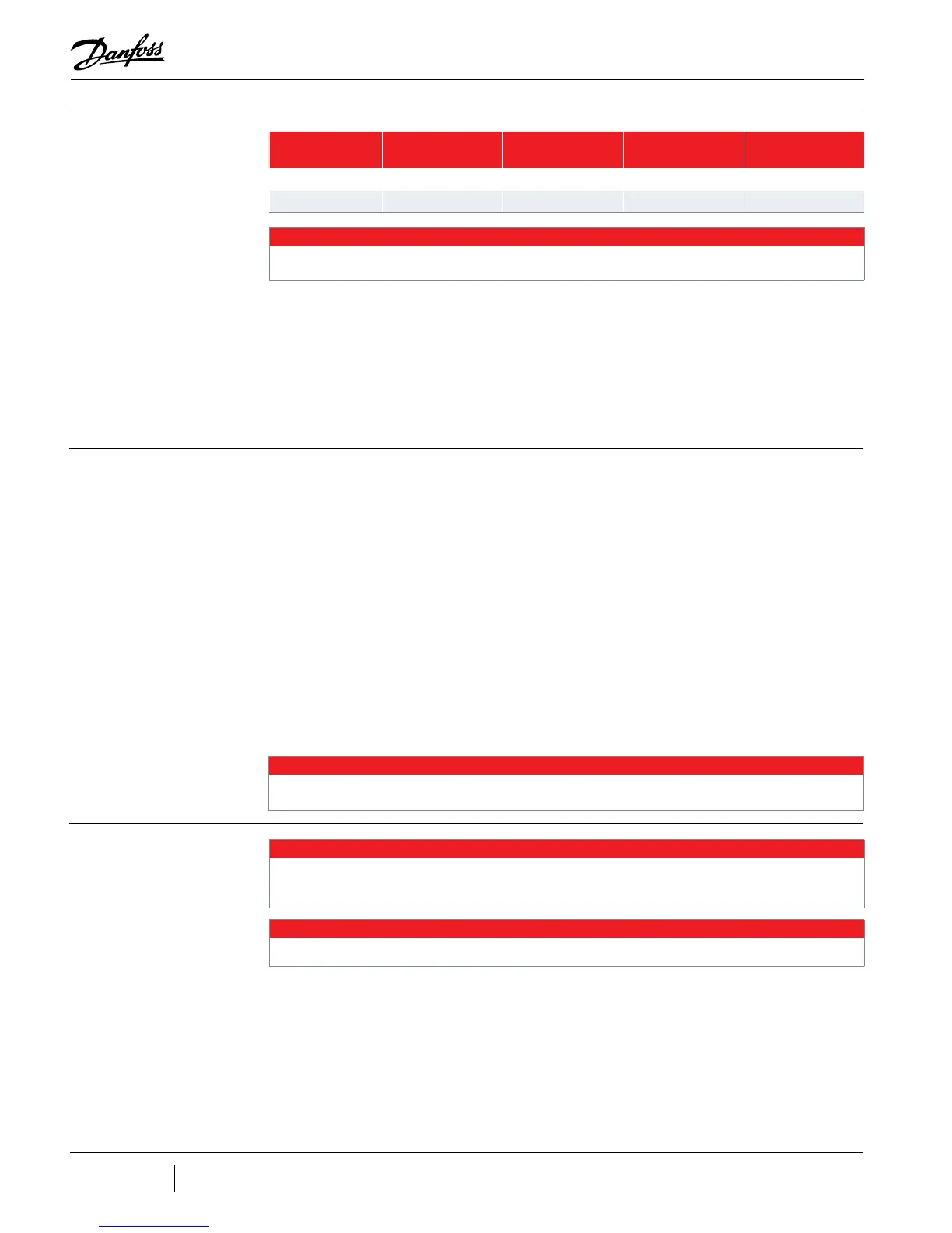
Table 13-1 - Recommended
Minimum Copper Tube Size
TT300/TG230 TT350/TG310 TT400/TG390 TT700/TG520
Suction 4" 4" 5" 5"
Discharge 2 5/8" 3 1/8" 4" 4"
NOTE
If steel pipe is used, the pipe must be selected to give the equivalent inside diameter to copper pipe.
Properly tapered trumpets with smooth transitions must be used to connect the compressor
anges to the pipework.
The discharge line exit transition should not be at an angle greater than eight degrees
inclusive. The suction line length should be straight for 1.5 times the pipe diameter before
entry into the compressor.
13.2 Economizer Option
13.3 Motor/Electronics
Cooling Requirements
Turbocor compressors use two stage centrifugal compression with interstage port
availability. This feature provides advantages of capacity and eciency improvement when
an economizer is installed. The improvements in eciency and capacity are a result of
further sub-cooling of the liquid refrigerant. Two types of economizer arrangements can be
used: sub-cooler or ash tank. See Figure 14-3 and Figure 14-4. Refrigerant must enter the
compressor through the economizer port in a “gas” state. Care must be taken to ensure that
no liquid enters the compressor.
To determine compressor capacity and eciency, the economizer performance rating
option is available in the Selection Software on the Customer Service and Support -
Performance Tools section of the DTC web page (www.turbocor.com). The circuit must
be properly designed to reect the specied heat exchanger approach with minimized
pressure drops across the liquid side and expansion side. Piping design, including expansion
device selection and pipe sizing, should be in accordance with best practices.
It is essential that compressor motor and power electronics cooling is available immediately
at start up. The compressor motor cooling liquid feed line must be congured and located
so that this occurs. Recommended minimum pipe size is 1/2" for all models. A larger size
may be necessary in some situations such as systems with low subcooling on start or
extended piping runs. A full ow lter / drier must be installed and a liquid sight glass must
be installed adjacent to each compressor. In multiple compressor systems, a single lter/
dryer may serve multiple compressors but each compressor must have a dedicated sight
glass.
NOTE
• Sub-cooled liquid must be fed to the motor/electronics cooling port of the compressor.
• It must be in a pure liquid state with a minimum of 6° F (3.5°C) sub cooled at the connection point to the motor/
electronics cooling port of the compressor.
NOTE
Filter dryer, sight glass and service valve must be tted in the motor-cooling liquid line.
NOTE
To prevent reverse rotation and potential bypass of gas through an idle compressor the economizer circuit must be isolated with
an automatically actuated valve which closes immediately upon compressor shut down.
 Loading...
