Page 22 of 108
M-AP-001-EN Rev. N
M-AP-001-EN Rev. N
Functional Description
3.3 Inlet Guide Vanes The Inlet Guide Vane (IGV) assembly is a variable-angle guiding device that is used for
capacity control. The IGV assembly consists of movable vanes and a motor. The vane
opening is determined by the BMCC and controlled by the Serial Driver. The IGV position can
vary between 0-110% where 0% is fully closed and 110% is fully open with the vanes at a 90°
angle.
3.4 Compressor Control
Overview
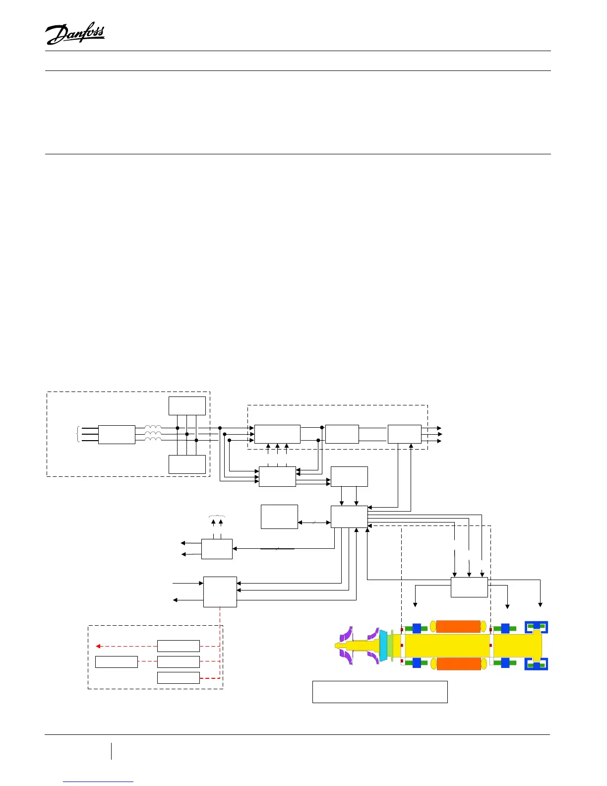
Figure 3-5 shows a functional block diagram of the compressor control and monitoring
system. Figure 3-7 displays the component locations. The major components include:
• Motor Drive
• Soft-Start Board
• Bearing Motor Compressor Controller (BMCC)
• Bearing PWM Amplifier
• Backplane
• Serial Driver
• HV DC-DC Converter
Figure 3-5 - Compressor
Control System Functional
Block Diagram
Backplane
2-3A
(Calibration)
Front
Radial
Bearing
Rear
Radial
Bearing
Axial
Bearing
2-3A
(Calibration)
2-3A
(Calibration)
Customer
Chiller Control
Communicati on s
Inter fac e
Diagnostic
Te rm inal
Internet
RS-485 Comms
to Chiller or Building
Management System
User Inte rface
Serial
Dri v er
Mo du le
+15VD C
+24VD C
To Motor Cooling Solenoids
To IGV St epp er Mot or
Compres sor
I/O
Boa rd
0-10VDC
0-10VDC
Compres sor
Inputs
Compres sor
Outputs
Bearing PWM
Amplifier
HV
+
not HV
-
+17VDC
not HV
-
+5 VDC
Control
Fee db ack
+15VD C
+24VDC
+5 VDC
+15VD C
Control
Fee db ack
Control
Fee db ack
Soft-Sta rt
Controller
0-12 VDC
nex t (+) DC bus
Variable
Frequency
(0-75 0Hz)
AC Voltage
To Stator
V
a
V
b
V
c
DC/DC
Conver te r
460-853 VDC
15 VAC
+24VD C
HV
+
(+ 250 VDC)
not HV
-
3-Phase
380-575VAC
50/60 Hz
+24VDC
Gati ng
Signals
Control
Fee db ack
Bearing
Motor
Compres sor
Controller
(BMCC)
Control
+5 VDC
+15VDC
-15 VDC
+15VDC
Ex ternal Ex pa nsi on Va lves
Shaft Posi tion Outputs
Surge
Suppressor
Harmoni c
Filte r
Line
Reac to r
EMI/EMC
Filte r
External Power Components
3-Phase
380-575VAC
50/60 Hz
Half-Controlled
Rectifier
DC Li nk
Capa citors
1.35*V
in
0 VDC
3-Phase
IGBT
Invert er
460-853 VDC
0 VDC
Motor Drive
Note:
All voltage levels shown have t he following error tolerance:
DC (except the D C bus): ±5%
AC : ±10%
 Loading...
