102 of 114
M-AP-001-EN Rev. Q
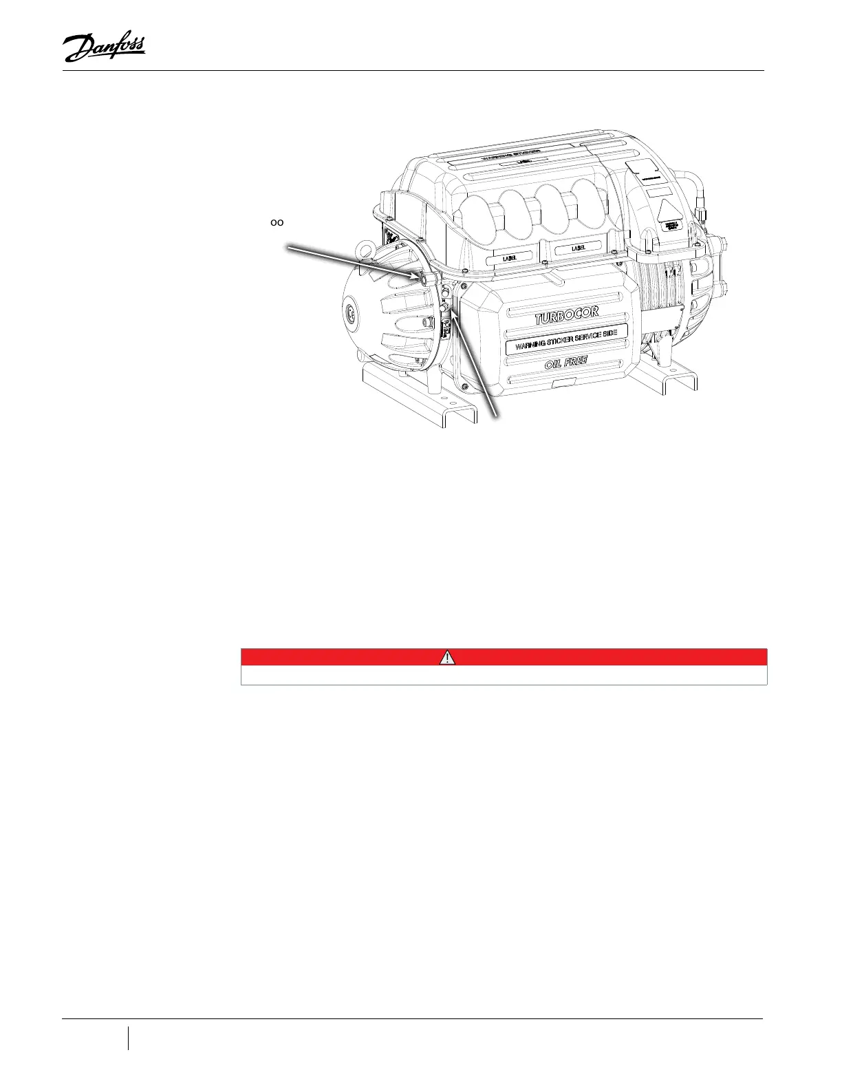
Figure 20-5 Motor-Cooling Connection and Access Port
20.6 Control Wiring
The compressor I/O board enables communication of control and status signals between the
compressor controller and external equipment. These signals include, among others, cooling demand,
input, stepper motor control inputs and outputs, alarm and interlock contacts, and Modbus protocol
communications.
20.6.1 Control Wiring Connections
Figure "Figure 4-1 Typical Control Wiring" on page 29 shows the control wiring connections to the
compressor I/O board. "Table 4-1 Control Wiring Details" on page 31 provides details for the module
terminal connections.
• • • CAUTION • • •
Incorrect wiring of the terminals can severely damage the module and other components.
The interface cable connects the compressor to the compressor I/O board. To connect the cable:
1. Plug the cable connector into connector J6 on the compressor I/O board.
• For RS-485 communication, the total length of the interface cable and control wiring can
be extended up to 100 meters (328 feet) (refer to "Figure 4-3 I/O Wiring Specifications"
on page 32). If the compressor is going to be monitored over an RS-232 line, the total
cable length between the compressor and the PC should not exceed 15 meters (50 feet).
Refer to "4.2 Interface Cable" on page 32.
Motor Cooling
Inlet
Schrader
Valves
 Loading...


