20 of 114
M-AP-001-EN Rev. Q
2.5 Configurations of the TTS/TGS/TTH/TGH Compressor Models
The compressor, motor, and power assemblies are packaged in design.
• • • CAUTION • • •
It is important to take all precautions to avoid refrigerant migration, especially on air-cooled units. If the compressor is filled with
liquid, there is a high risk of bearing damage, thus putting the compressor out of service. The compressor warranty will be voided
if the compressor is damaged due to refrigerant migration.
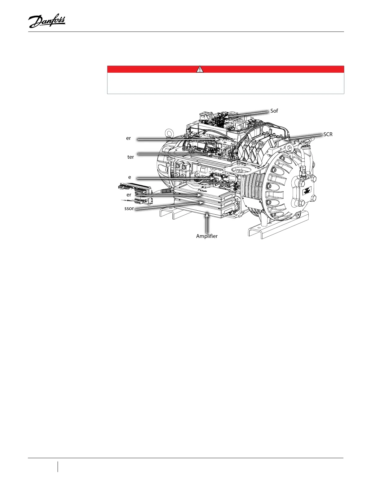
Figure 2-3 Major Components
2.6 Compressor Module
This section provides a brief overview of the Compressor Module.
The Compressor Module is comprised of three (3) portions:
• Aerodynamics - The aerodynamics portion manages the refrigerant compression process from
the suction to the discharge including the inlet guide vane assembly.
• Motor - The motor portion contains a direct-drive, high-efficiency, permanent-magnet
synchronous motor powered by pulse-width-modulating (PWM) voltage supply. The high-speed
variable-frequency operation that affords high-speed efficiency, compactness and soft start
capability. Motor cooling is by liquid refrigerant injection.
• Electronics - The electronics is divided into two (2) sections: Power electronics located on the
top of the compressor including soft-start, DC-DC, Silicon-Controlled Rectifier (SCR), capacitors,
and inverter. Control electronics located on the side of the compressor including: backplane,
BMCC, serial driver, and PWM.
PWM Amplifier
Inverter
SCRs
Soft Start Board
DC-DC
Converter
Backplane
Serial Driver
Bearing Motor Compressor
Controller (BMCC)
 Loading...


