VLT
®
Series 3500
109
DANGER
!
Before opening the enclosure to install any components, be
sure all power has been removed from the drive. Allow at
least 14 minutes for the capacitors to discharge before
touching any internal components.
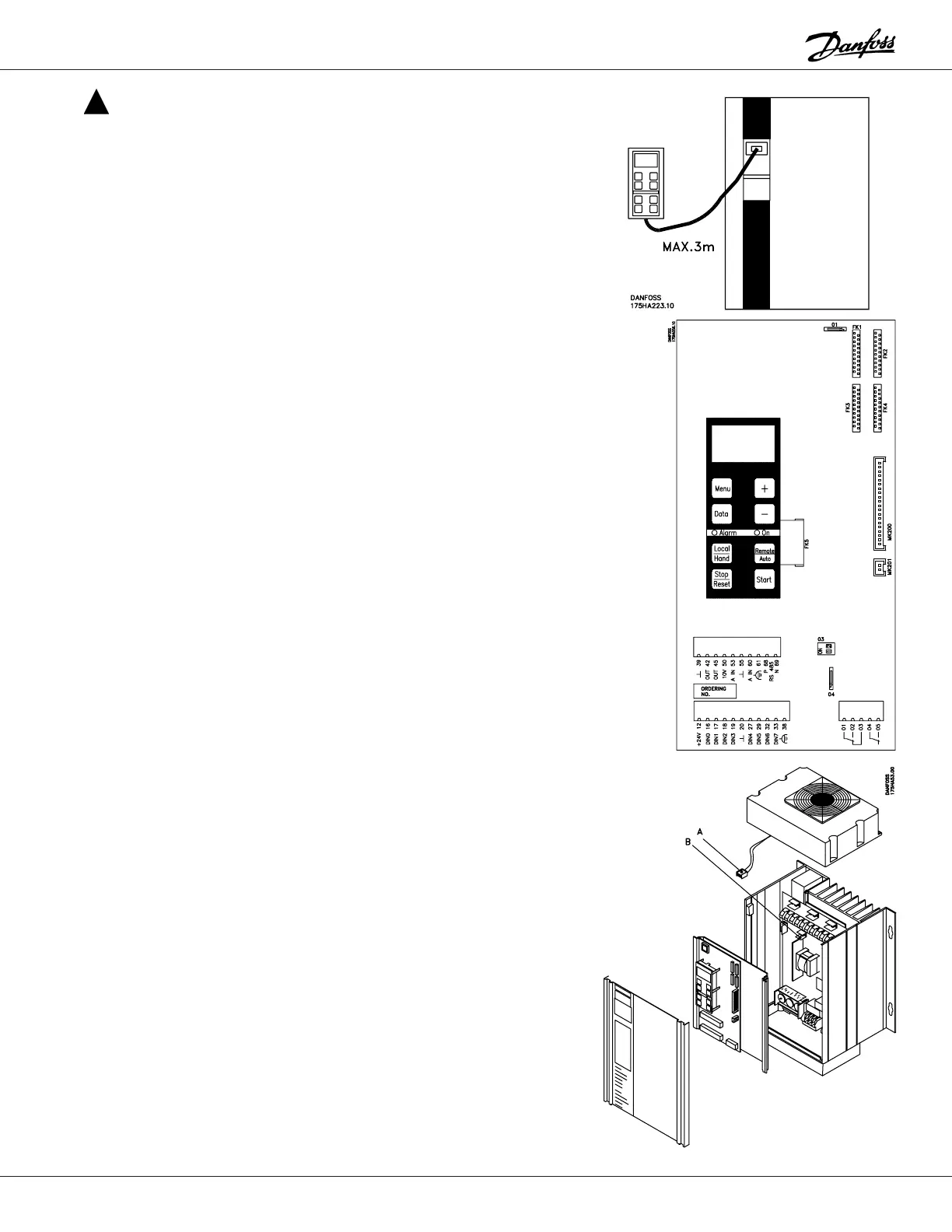
External Mounting of Display
The control panel can be mounted remotely by means of an
optional adapter and cable. The cable is 10 feet long.
Longer cables are not recommended.
The control panel and its mounting surfaces meet the re-
quirements for NEMA 12. The hole size required is 4.41 x
2.01 ± 0.02 inch.
Installation of Option Cards
There is a provision to mount an option card next to the
control card in the drive. Mount the option card using the
groove in the right-hand side of the aluminium tray and the
two screws provided with the card, if not factory installed.
The electrical connections between the option card and the
standard control card is through plugs FK1 through FK4.
Mounting of Optional Fan
Some applications may have an optional fan that must be
installed, if it is not factory installed.
To install the fan, unplug the ribbon connector and the
small cable and the ground wire from the control card.
Remove the control card and the shield behind it.
Position the fan on the aluminum extrusion, making sure
that the fan mounting holes are aligned with the enclosure.
Plug the fan connector into the matching connector on the
power board.
Reinstall the control card carefully. Plug in the ribbon
connector, the small cable and the ground wire.