VLT
®
Series 3500
87
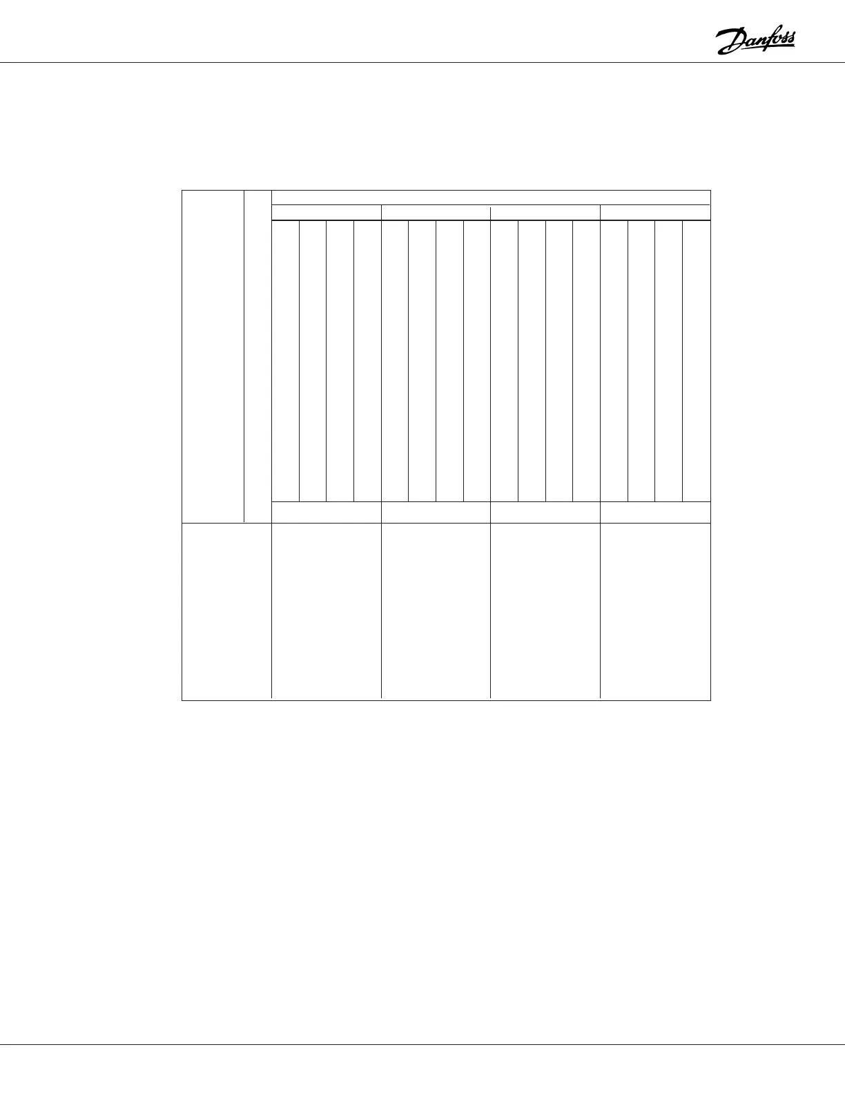
Control Word, bytes 5 through 8 in the message. The control word is used to send control commands from the controller
to the drive. According to the data format, 1 byte consists of 8 databits, but in the control word only the 4 least significant
bits of each byte are used, which means that ASCII characters from A to O can be used. The table below gives the meaning of
the individual bits in the control word.
@
A
B
C
D
E
F
G
H
I
J
K
L
M
N
O
P
0
/
1
15 14 13 12 11 10 09 08 07 06 05 04 03 02 01 00
0000000000000000
0001000100010001
0010001000100010
0011001100110011
0100010001000100
0101010101010101
0110011001100110
0111011101110111
1000100010001000
1001100110011001
1010101010101010
1011101110111011
1100110011001100
1101110111011101
1110111011101110
1111111111111111
Bit 00,
OFF1/ON1
:
Ordinary ramp stop using the ramp time in parameter 216.
Bit 00 = “0” causes a stop; bit 00 = “1” means that the drive
is able to start if the other conditions for doing so have
been fulfilled.
Bit 01,
OFF2/ON2:
Coast stop. Bit 01 = “0” causes a coast t stop; bit 01 = “1”
means that the frequency converter is able to start if the
other conditions for doing so have been fulfilled.
Bit 02,
OFF3/ON3:
Quick-stop using the ramp time in parameter 218. Bit 02 =
“0” causes a quick-stop; bit 02 = “1” means that the drive is
able to start if the other conditions for doing so have been
fulfilled.
Bit 03,
COAST/ENABLED:
Coast stop. Bit 03 = “0” causes a stop; bit 03 = “1”drive is
able to start if the other conditions for doing so have been
fulfilled. Note: In parameter 503 a choice is made as to how
bit 03 is to be combined with the corresponding function on
the digital inputs.
Bit 04,
QUICK-STOP/RAMP:
Quick-stop using the ramp time in parameter 218. Bit 04 =
“0” causes a quick-stop; bit 04 = “1” means that the drive is
able to start if the other conditions for doing so have been
fulfilled.
X = Indifferent; if P is used in a group of 4 bits, the current status is maintained. Only the groups with characters ≠ P are activated.
Bit 10 = 0 means that there is no change from the current status.
ASCII
CONTROL WORD
Byte 8 Byte 7 Byte 6 Byte 5
NCCNNDJ JNRHQCOOO
0HHOOAOOOAOUOFFF
OO TGG ML IA F FF
F I I FFA FPDCS
UCCUU 21U KT321
NEENNN NS / -
C CCOOOCT S////
TOOTTTFFTORT
IFFI I FFIPAOEOOO
O OOV O MPNNNN
NSSNNA/ / N / P A
/EE L /B321
RTT//IOO/SE L
E-- DNN TNRE
VUUCS RAAAD
EPPAL / ERBM
RTO STLP
S21CWV E E
IHDATD
N-OL
GUWI
PND