35
VLT
®
Series 3500
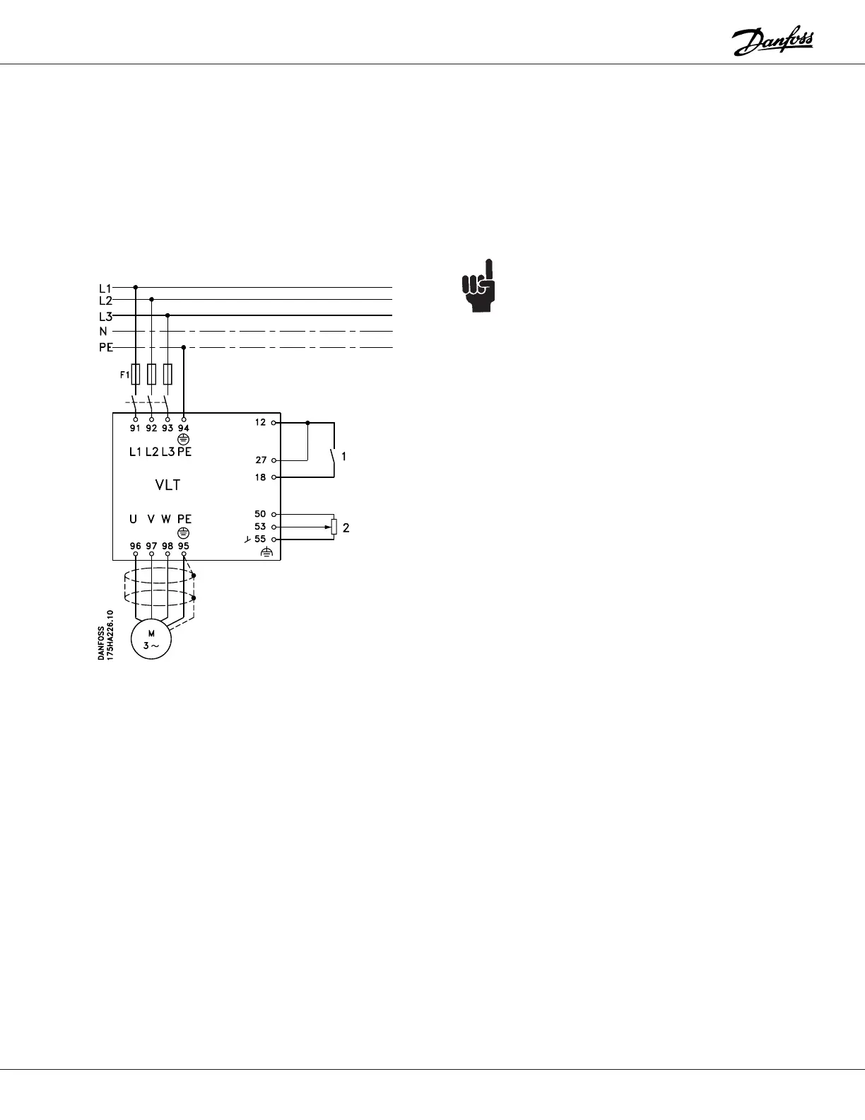
Typical Wiring and Setup Examples
The following examples show some typical HVAC
installations. The power and control connections, and the
parameter settings for each example are shown. Details
of the parameters are in the Drive Setup section. It may
helpful to find the example closest to the requirements of
your installation and use it as a guide.
Example 1:
A fan is to be speed controlled between 6 and 60 Hz. A 0
to 10 V DC potentiometer is used as the control signal.
The following must be programmed:
Function Parameter # Parameter Value Data Value #
Safety interlock 003 KEY HOA w. stp [1]
Minimum frequency 201 6 Hz
maximum frequency 202 60 Hz
Reference (voltage) 412 0 to 10 V DC [2]
Reference (current) 413 No operation [0]
NOTE:
A shield for control wires is to be connected in
accordance with the installation instructions.
All settings are based on factory settings.
Be sure to check the motor data settings (parameters
104, 105 and 107, or the Quick Setup menu items 1, 2
and 3). They must be set based upon the actual motor
used.
1 = Start/Stop
2 = 1 kW potentiometer
External safety interlocks can be connected between
terminals 12 and 27.