VLT
®
Series 3500
83
410 Terminal 04 Relay Output (RELAY 04)
Value:
Control ready (CONTROL READY) [0]
Unit ready (UNIT READY) [1]
Ready - remote control (UNT RDY RCTL) [2]
Enabled (ENABLED noWR) [3]
★ Running (RUNNING) [4]
Running, no warning (RUNNING noWR) [5]
Running in range, no warning (RUNinRANGE) [6]
Speed = reference, no warning (RUN@REF noWR) [7]
Alarm (ALARM) [8]
Alarm or warning (ALARM or WARN) [9]
Current limit (CURRENT LIMIT) [10]
Out of frequency range (OUT FREQ RGE) [11]
Warning of F low (LO FREQ. WARN) [12]
Warning of F high (HI FREQ. WARN) [13]
Out of current range (OUT CURR RGE) [14]
Warning of I low (LO CURR. WARN) [15]
Warning of I high (HI CURR. WARN) [16]
Motor thermal overload (MOT.THERM.WARN) [17]
Ready and no motor thermal overload
(READY+MOT.OK) [18]
Ready and remote control (RDY+MOT+REM) [19]
Ready and no over-/undervoltage (RDY+DC V OK) [20]
Idle running current (NO LOAD CURR) [21]
Function:
Relay outputs 01 and 04 can be used for indicating status
and warnings.
The relay is activated when the conditions for the different
data values are fulfilled. When relay 4 is activated, there is
a connection between terminals 4 and 5.
Description of choice:
[0]-[16] See explanations under parameter 407.
[17]-[21] See explanations under parameter 409.
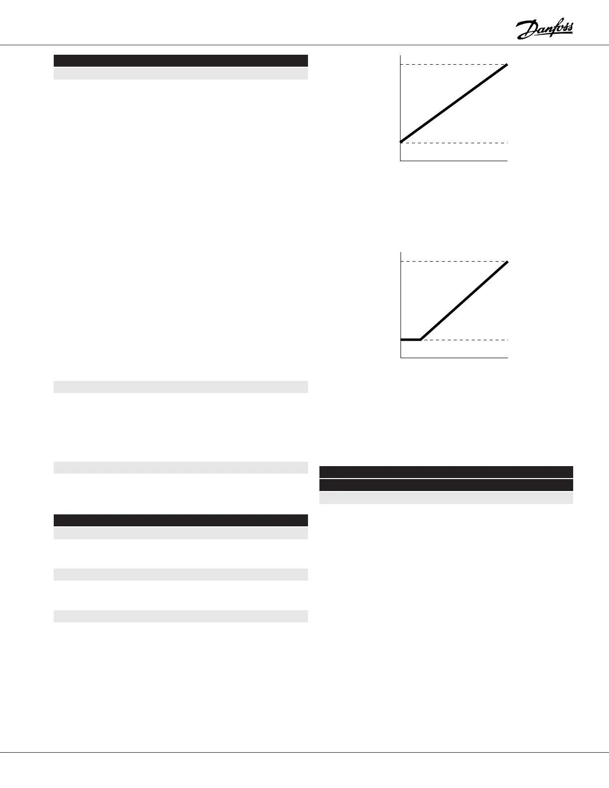
411 Analog Reference Type (ANALOG REFTYPE)
Value:
★ Linear between minimum and maximum (LINEAR) [0]
Proportional with lower limit (PROP W/MIN.) [1]
Function:
It is possible to select different forms of how the output fre-
quency is to depend on the analog reference signal.
Description of choice:
Used for deciding how the drive is to follow an analog refer-
ence signal, see graphs in next column.
Output Speed
Speed Reference Signal
Min.
(parameter 201)
Max.
(parameter 202)
Min.
0 V
4 mA
0 mA
Max.
10 V
20 m
20 m
★ = ROM default setting. ✔ = Normal Danfoss setup. Text in ( ) = display text. Figures in [ ] are used when communicating with the bus.
Output Speed
Speed Reference Signal
Min.
(parameter 201)
Max.
(parameter 202)
Min.
0 V
4 mA
0 mA
Max.
10 V
20 m
20 m
Choice [0]
Choice [1]
412 Terminal 53 Analog Input Voltage
(INPUT #53)
Value:
✔ No operation (NO OPERATION) [0]
★ 0 to 10 V (0 to 10 V DC) [1]
10 to 0 V (10 to 0 V DC) [2]
2 to 10 V (2 to 10 V DC) [3]
10 to 2 V (10 to 2 V DC) [4]
1 to 5 V (1 to 5 V DC) [5]
5 to 1 V (5 to 1 V DC) [6]