37
VLT
®
Series 3500
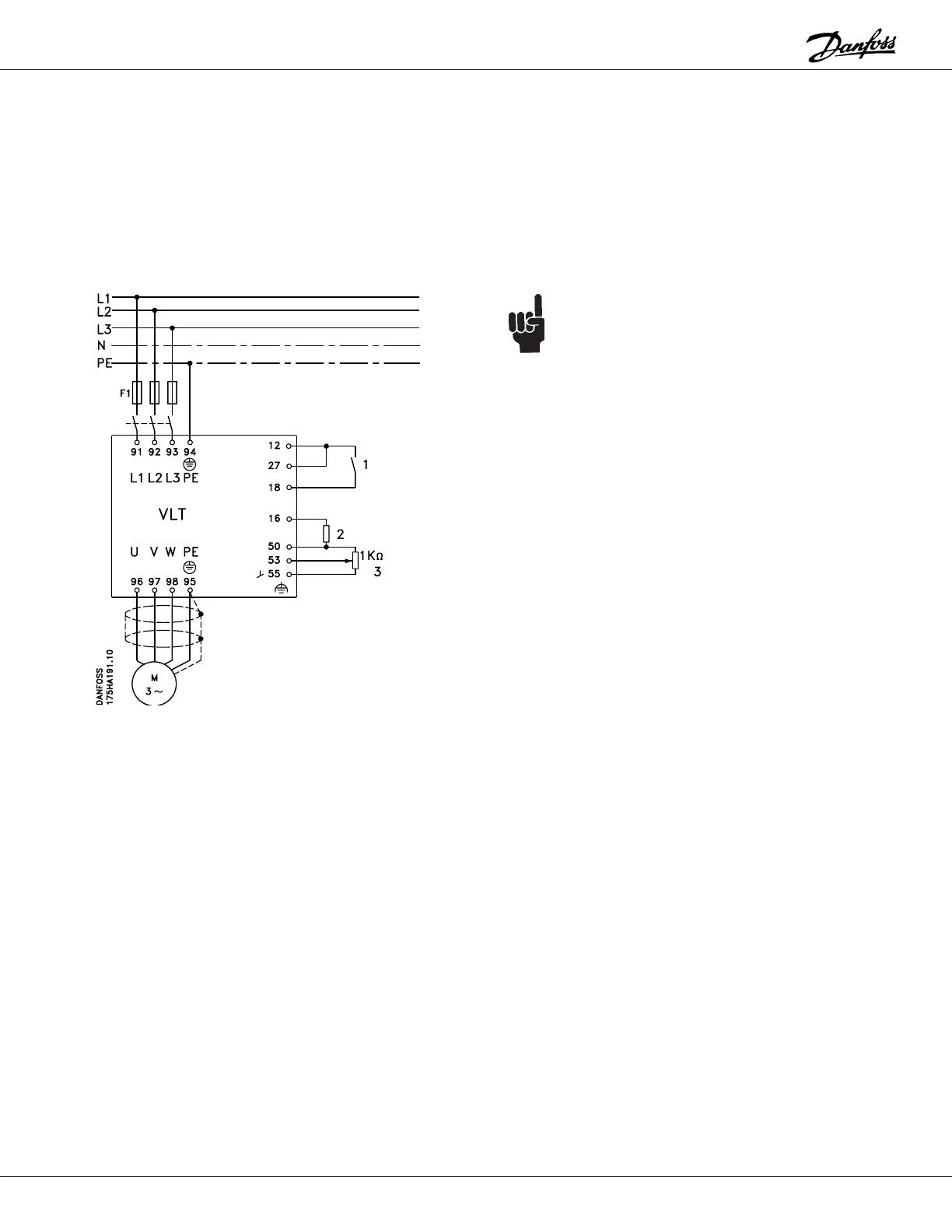
Example 3:
A fan is to be controlled manually by means of a 0 to 10
V DC potentiometer corresponding to 10 to 60 Hz.
A thermistor is installed in the motor to obtain optimum
motor protection. The thermistor is to be connected to the
drive to shut down the drive in case of motor
overtemperature.
The following must be programmed:
Function Parameter # Parameter Value Data Value #
Safety interlock 003 KEY HOA w. stp [1]
Minimum frequency 201 10 Hz
Maximum frequency 202 60 Hz
Thermistor on term. 16 400 THERMISTOR [4]
REFERENCE (voltage) 412 0 to 10 V DC [1]
REFERENCE (current) 413 No operation [0]
NOTE:
A shield for control wires is to be connected in
accordance with the installation instructions.
All settings are based on factory settings.
Be sure to check the motor data settings (parameters
104, 105 and 107, or the Quick Setup menu items 1, 2
and 3). They must be set based upon the actual motor
used.
1 = Start/Stop
2 = Thermistor
3 = 1 k W Potentiometer
External safety interlocks can be connected between
terminals 12 and 27.