EasyManuals Logo

Danfoss vlt aqua Instruction

Danfoss vlt aqua
206 pages
To Next Page IconTo Next Page
To Previous Page IconTo Previous Page
Page #166 background imageLoading...
Page #166 background image
7.1.2 Network Connection
Connect the adjustable frequency drive to the RS-485 network as follows (see also diagram):
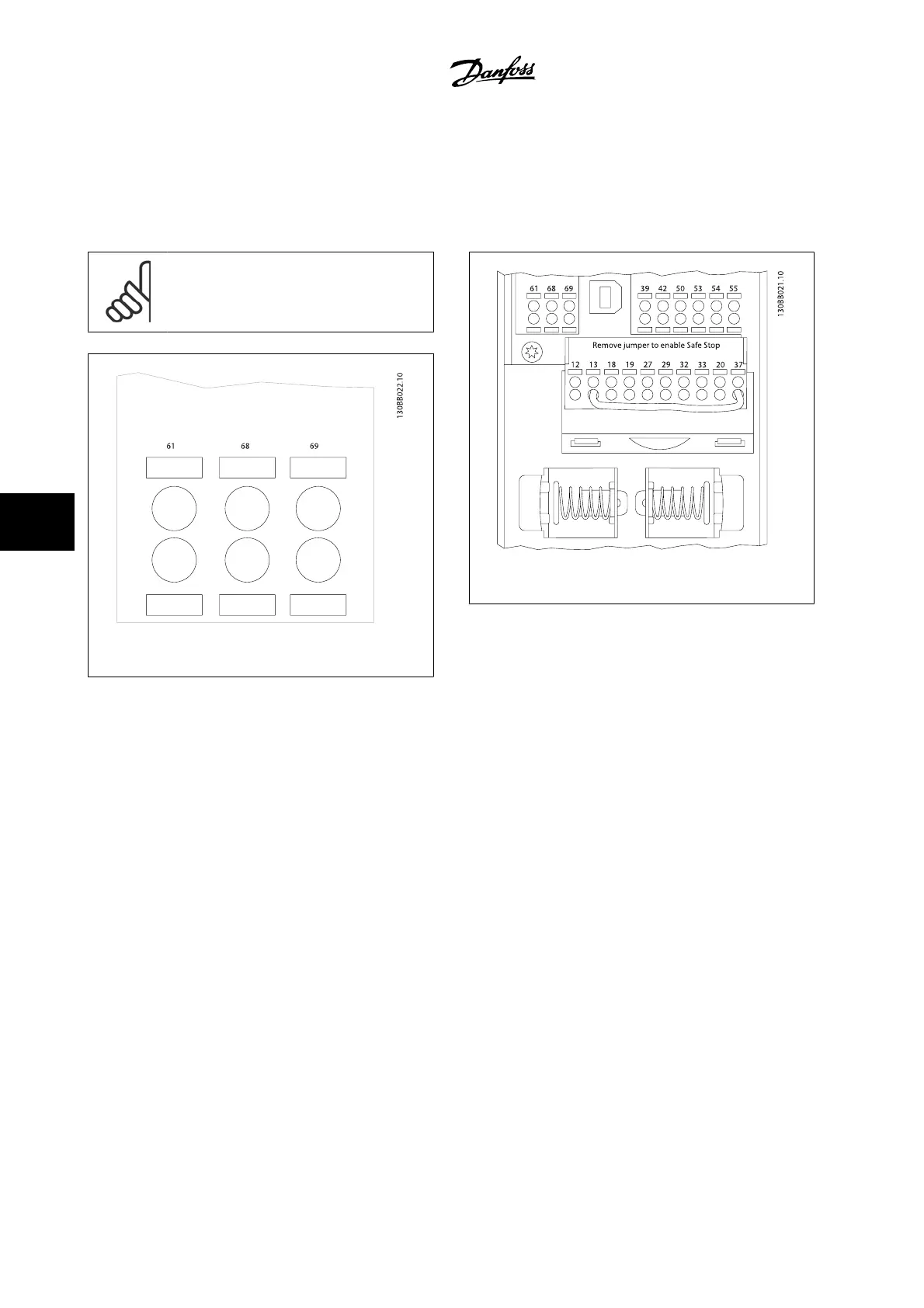
1. Connect signal wires to terminal 68 (P+) and terminal 69 (N-) on the main control board of the adjustable frequency drive.
2. Connect the cable screen to the cable clamps.
NOTE!
Shielded, twisted-pair cables are recommended in or-
der to reduce noise between conductors.
Figure 7.1: Network Terminal Connection
Figure 7.2: Control card terminals
7 RS-485 Installation and Set-up
VLT AQUA Low Harmonic Drive Instruction
Manual
7-2
MG.20.T1.22 - VLT
®
is a registered Danfoss trademark
7

Table of Contents

Other manuals for Danfoss vlt aqua

Questions and Answers:

Question and Answer IconNeed help?

Do you have a question about the Danfoss vlt aqua and is the answer not in the manual?

Danfoss vlt aqua Specifications

General IconGeneral
Supply Voltage200-240V, 380-500V, 525-600V
EnclosureIP20
FeaturesEnergy optimization
ApprovalsCE, UL, cUL
Input Voltage Range200-240V, 380-500V, 525-600V
Output Voltage Range0 to supply voltage
Protection FeaturesOvervoltage, Undervoltage, Overcurrent, Short circuit, Ground fault
Communication InterfacesPROFIBUS
Cooling MethodAir-cooled

Related product manuals