if any one feedback is below the setpoint and decrease the
speed of the fan if all feedbacks are above the setpoint.
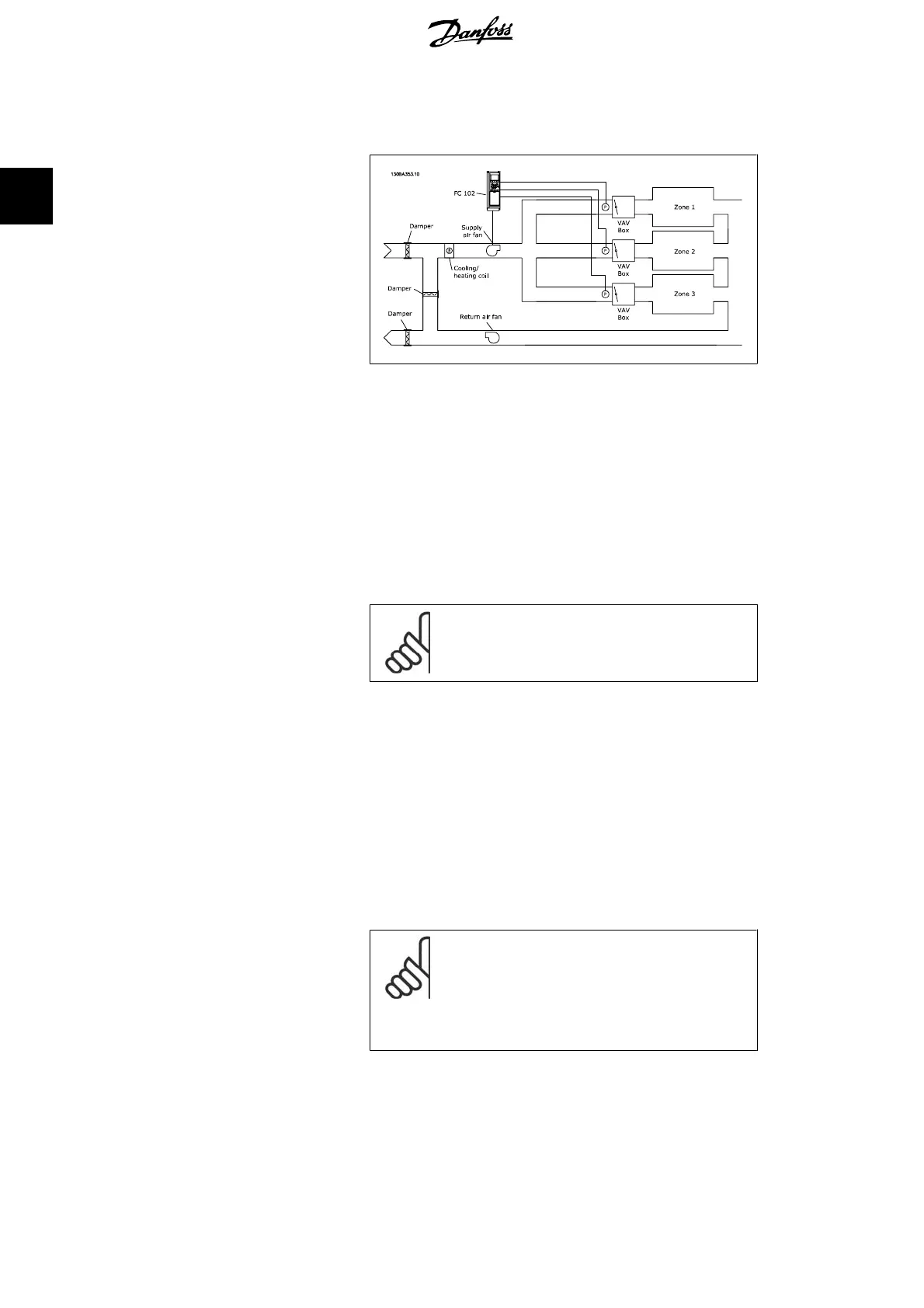
Example 2 – Multi zone, multi setpoint
The previous example can be used to illustrate the use of multi
zone, multi setpoint control. If the zones require different pres-
sures for each VAV box, each setpoint may be specified in par.
20-21, 20-22 and 20-23. By selecting
Multi setpoint minimum
,
[5], in par. 20-20, Feedback Function, the PID Controller will
increase the speed of the fan if any one of the feedbacks is be-
low its setpoint and decrease the speed of the fan if all feed-
backs are above their individual setpoints.
Sum
[0] sets up the PID Controller to use the sum of Feedback
1, Feedback 2 and Feedback 3 as the feedback.
NB!
Any unused feedbacks must be set to
No Func-
tion
in par. 20-00, 20-03, or 20-06.
The sum of Setpoint 1 and any other references that are enabled
(see par. group 3-1*) will be used as the PID Controller’s set-
point reference.
Difference
[1] sets up the PID Controller to use the difference
between Feedback 1 and Feedback 2 as the feedback. Feedback
3 will not be used with this selection. Only setpoint 1 will be
used. The sum of Setpoint 1 and any other references that are
enabled (see par. group 3-1*) will be used as the PID
Controller’s setpoint reference.
Average
[2] sets up the PID Controller to use the average of
Feedback 1, Feedback 2 and Feedback 3 as the feedback.
NB!
Any unused feedbacks must be set to
No Func-
tion
in par. 20-00, 20-03, or 20-06. The sum of
Setpoint 1 and any other references that are en-
abled (see par. group 3-1*) will be used as the PID
Controller’s setpoint reference.
Minimum
[3] sets up the PID Controller to compare Feedback
1, Feedback 2 and Feedback 3 and use the lowest value as the
feedback.
2. Parameter Description VLT
®
AQUA Drive Programming Guide
178
MG.20.O2.02 - VLT
®
is a registered Danfoss trademark
2
 Loading...


