1.1.4. Display Mode - Selection of Displayed Variables
It is possible to toggle between three status read-out screens by pressing the [Status] key.
Operating variables with different formatting are shown in each status screen - see below.
Several measurements can be linked to each of the operating variables. Define the links via par.
0-20, 0-21, 0-22, 0-23, and 0-24.
Each readout parameter selected in par. 0-20 to par. 0-24 has its own scale and digits after a
possible decimal point. By larger numeric value of a parameter fewer digits are displayed after the
decimal point.
Ex.: Current readout below: 5.25 A; 15.2 A 105 A.
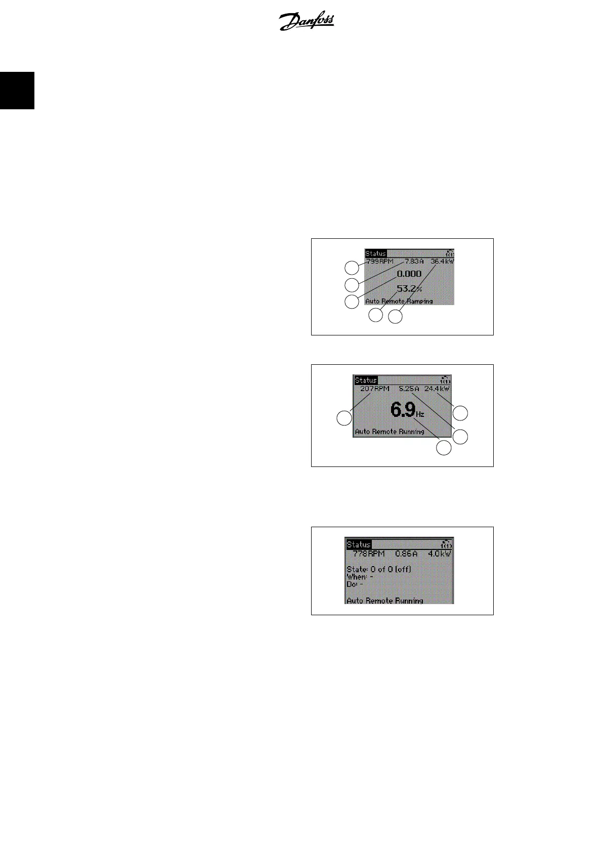
Status screen I
This read-out state is standard after start-up
or initialization.
Use [INFO] to obtain information about the
measurement links to the displayed operating
variables /1.1, 1.2, 1.3, 2, and 3).
See the operating variables shown in the
screen in this illustration. 1.1, 1.2 and 1.3 are
shown in small size. 2 and 3 are shown in me-
dium size.
130BP041.10
1.1
1.3
2
1.2
3
Status screen II:
See the operating variables (1.1, 1.2, 1.3, and
2) shown in the screen in this illustration.
In the example, Speed, Motor current, Motor
power and Frequency are selected as varia-
bles in the first and second.
1.1, 1.2 and 1.3 are shown in small size. 2 is
shown in large size.
In both status screen I and II it is possible to
select other operating variables by pressing
▲ or ▼ .
130BP062.10
2
1.2
1.3
1.1
Status screen III:
This state displays the event and action of the
Smart Logic Control. For further information,
see section
Smart Logic Control
.
130BP063.10
1.1.5. Parameter Set-Up
The frequency converter can be used for practically all assignments, thus offering a significant
number of parameters. The series offers a choice between two programming modes - a Quick
Menu mode and a Main Menu mode.
The latter provides access to all parameters. The former takes the user through a few parameters
making it possible to program the majority of water/ wastewater applications.
Regardless of the mode of programming, you can change a parameter both in the Quick Menu
mode and in the Main Menu mode.
1. How to Programme VLT
®
AQUA Drive Programming Guide
10
MG.20.O2.02 - VLT
®
is a registered Danfoss trademark
1
 Loading...


