3. Parameter Lists
3.1. Parameter Options
3.1.1. Default settings
Changes during operation
”TRUE” means that the parameter can be changed while the frequency converter is in operation
and “FALSE” means that the frequency converter must be stopped before a change can be made.
4-Set-up
'All set-up': the parameter can be set individually in each of the four set-ups, i. e. one single
parameter can have four different data values.
’1 set-up’: data value will be the same in all set-ups.
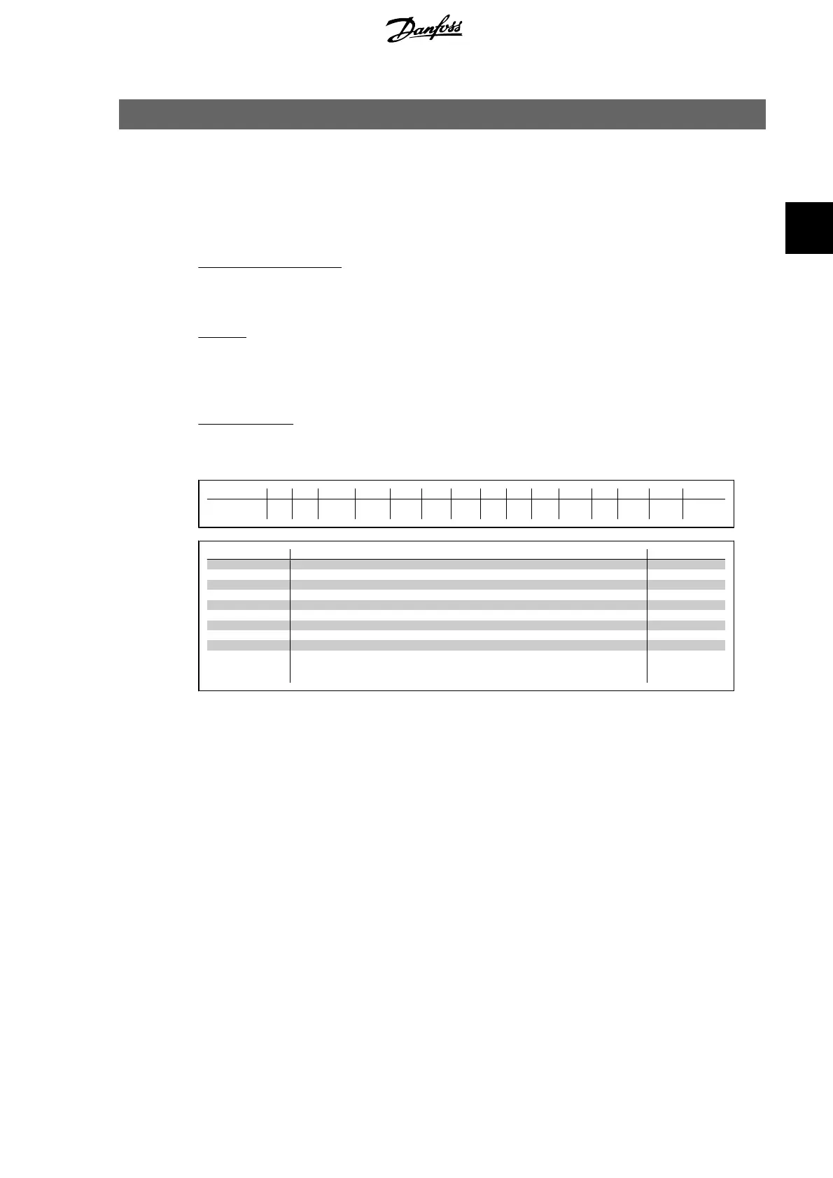
Conversion index
This number refers to a conversion figure used when writing or reading by means of a frequency
converter.
Conv. index 100 67 6 5 4 3 2 1 0 -1 -2 -3 -4 -5 -6
Conv. factor 1 1/60 100000
0
100000 10000 1000 100 10 1 0.1 0.01 0.00
1
0.000
1
0.0000
1
0.000001
Data type Description Type
2 Integer 8 Int8
3 Integer 16 Int16
4 Integer 32 Int32
5 Unsigned 8 Uint8
6 Unsigned 16 Uint16
7 Unsigned 32 Uint32
9 Visible String VisStr
33 Normalized value 2 bytes N2
35 Bit sequence of 16 boolean variables V2
54 Time difference w/o date TimD
SR = Size related
VLT
®
AQUA Drive Programming Guide 3. Parameter Lists
MG.20.O2.02 - VLT
®
is a registered Danfoss trademark
257
3
 Loading...


