3.17.6 16-6* Inputs and Outputs
Parameters for reporting the digital and analog IO ports.
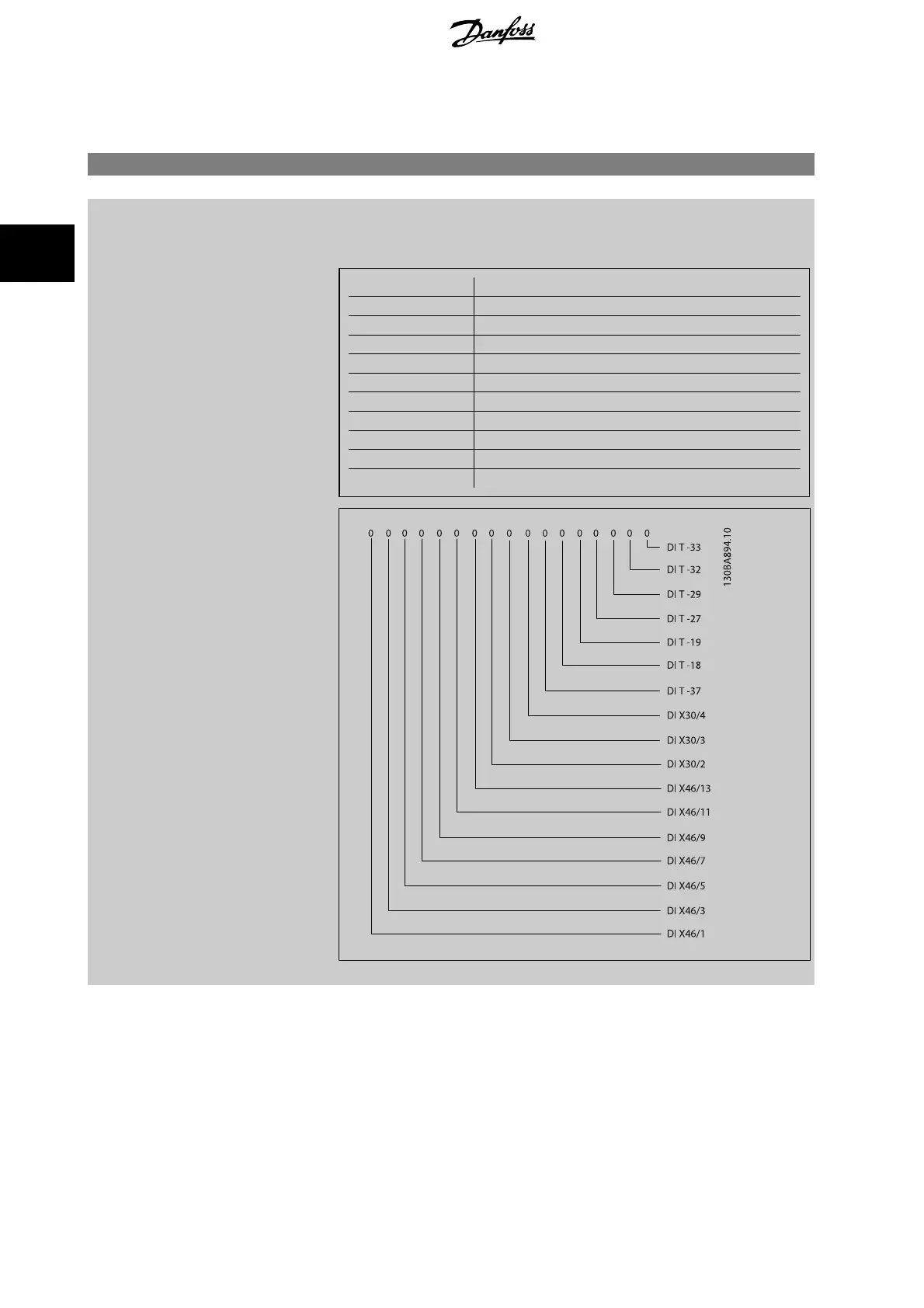
16-60 Digital Input
Range: Function:
0 N/A* [0 - 1023 N/A] View the signal states from the active digital inputs. Example: Input 18 corresponds to bit no. 5, ‘0’
= no signal, ‘1’ = connected signal. Bit 6 works in the opposite way, on = '0', off = '1' (safe stop
input).
Bit 0 Digital input term. 33
Bit 1 Digital input term. 32
Bit 2 Digital input term. 29
Bit 3 Digital input term. 27
Bit 4 Digital input term. 19
Bit 5 Digital input term. 18
Bit 6 Digital input term. 37
Bit 7 Digital input GP I/O term. X30/4
Bit 8 Digital input GP I/O term. X30/3
Bit 9 Digital input GP I/O term. X30/2
Bit 10-63 Reserved for future terminals
3 Parameter descriptions FC 300 Programming Guide
216
MG.33.M8.02 - VLT
®
is a registered Danfoss trademark
3

 Loading...


