3.3.4 1-3* Adv. Motor Data
Parameters for advanced motor data. The motor data in par. 1-30
Stator Resistance (Rs)
to par. 1-39
Motor Poles
must match the relevant motor in order
to run the motor optimally. The default settings are figures based on common motor parameter values from standard motors. If the motor parameters
are not set correctly, a malfunction of the frequency converter system may occur. If the motor data is not known, running an AMA (Automatic Motor
Adaptation) is recommended. See the
Automatic Motor Adaptation
section in the Design Guide. The AMA sequence will adjust all motor parameters except
the moment of inertia of the rotor and the iron loss resistance (par. 1-36
Iron Loss Resistance (Rfe)
).
Par. 1-3* and par. 1-4* cannot be adjusted while the motor is running.
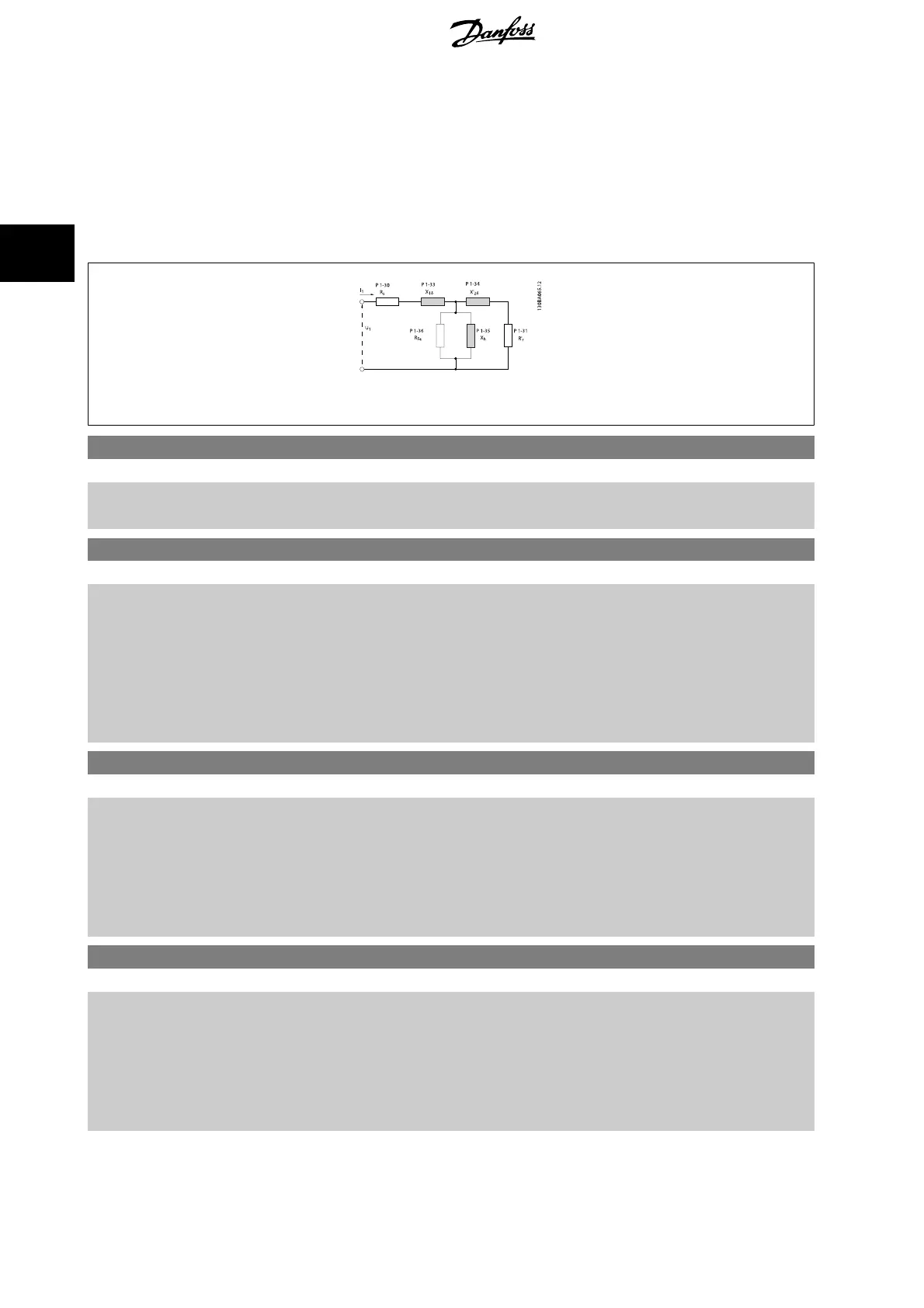
Illustration 3.1: Motor equivalent diagram for an asynchronous motor
1-30 Stator Resistance (Rs)
Range: Function:
Application
dependent*
[Application dependant] Set the stator resistance value. Enter the value from a motor data sheet or perform an AMA on a
cold motor.
1-31 Rotor Resistance (Rr)
Range: Function:
Application
dependent*
[Application dependant] Fine-tuning R
r
will improve shaft performance. Set the rotor resistance value using one of these
methods:
1. Run an AMA on a cold motor. The frequency converter will measure the value from the
motor. All compensations are reset to 100%.
2. Enter the R
r
value manually. Obtain the value from the motor supplier.
3. Use the R
r
default setting. The frequency converter establishes the setting on the basis of
the motor nameplate data.
1-33 Stator Leakage Reactance (X1)
Range: Function:
Application
dependent*
[Application dependant] Set the stator leakage reactance of the motor using one of these methods:
1. Run an AMA on a cold motor. The frequency converter will measure the value from the
motor.
2. Enter the X
1
value manually. Obtain the value from the motor supplier.
3. Use the X
1
default setting. The frequency converter establishes the setting on the basis of
the motor name plate data.
1-34 Rotor Leakage Reactance (X2)
Range: Function:
Application
dependent*
[Application dependant] Set the rotor leakage reactance of the motor using one of these methods:
1. Run an AMA on a cold motor. The frequency converter will measure the value from the
motor.
2. Enter the X
2
value manually. Obtain the value from the motor supplier.
3. Use the X
2
default setting. The frequency converter establishes the setting on the basis of
the motor name plate data.
3 Parameter descriptions FC 300 Programming Guide
50
MG.33.M8.02 - VLT
®
is a registered Danfoss trademark
3

 Loading...


