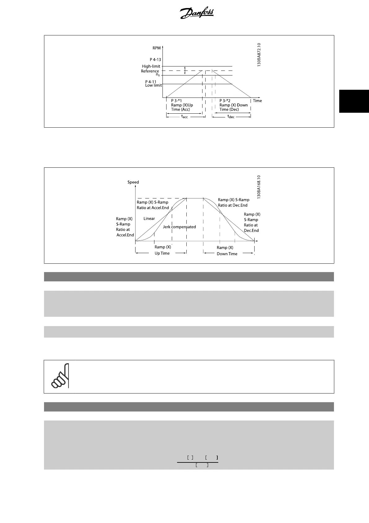
If S-ramps are selected then set the level of non-linear jerk compensation required. Set jerk compensation by defining the proportion of ramp-up and
ramp-down times where acceleration and deceleration are variable (i.e. increasing or decreasing). The S-ramp acceleration and deceleration settings are
defined as a percentage of the actual ramp time.
3-40 Ramp 1 Type
Option: Function:
Select the ramp type, depending on requirements for acceleration/deceleration.
A linear ramp will give constant acceleration during ramping. An S-ramp will give non-linear accel-
eration, compensating for jerk in the application.
[0] * Linear
[1] S-ramp Const Jerk Acceleration with lowest possible jerk.
[2] S-ramp Const Time S-ramp based on the values set in par. 3-41
Ramp 1 Ramp up Time
and par. 3-42
Ramp 1 Ramp
Down Time
.
NB!
If S-ramp [1] is selected and the reference during ramping is changed the ramp time may be prolonged in order to realize a jerk free
movement which may result in a longer start or stop time.
Additional adjustment of the S-ramp ratios or switching initiators may be necessary.
3-41 Ramp 1 Ramp up Time
Range: Function:
Application
dependent*
[Application dependant] Enter the ramp-up time, i.e. the acceleration time from 0 RPM to the synchronous motor speed n
S
.
Choose a ramp-up time such that the output current does not exceed the current limit in
par. 4-18
Current Limit
during ramping. The value 0.00 corresponds to 0.01 sec. in speed mode.
See ramp-down time in par. 3-42
Ramp 1 Ramp Down Time
.
Par
. 3 − 41 =
t
acc
s
x
n
s
RPM
ref
RPM
FC 300 Programming Guide 3 Parameter descriptions
MG.33.M8.02 - VLT
®
is a registered Danfoss trademark
77
3

 Loading...


