Sends an inverted stop signal when the precise stop function is activated in parameter 1-83 Precise Stop Func-
tion. Precise stop inverse function is available for terminals 18 or 19.
Use when [0] Precise ramp stop is selected in parameter 1-83 Precise Stop Function. Precise start, stop is availa-
ble for terminals 18 and 19. Precise start ensures that the rotor turning angle from standing still to reference
is the same for each start (for same ramp time, same setpoint). This function is the equivalent to the precise
stop where the rotor turning angle from reference to standstill is the same for each stop. When using param-
eter 1-83 Precise Stop Function option [1] Cnt stop with reset or [2] Cnt stop w/o reset: The drive needs a precise
stop signal before reaching the value of parameter 1-84 Precise Stop Counter Value. If this signal is not sup-
plied, the drive does not stop when the value in parameter 1-84 Precise Stop Counter Value is reached. Trigger
precise start, stop by a digital input. The function is available for terminals 18 and 19.
Increases reference value by percentage (relative) set in parameter 3-12 Catch up/slow Down Value.
Reduces reference value by percentage (relative) set in parameter 3-12 Catch up/slow Down Value.
Precise stop function in parameter 1-83 Precise Stop Function acts as counter stop or speed-compensated
counter stop with or without reset. Set the counter value in parameter 1-84 Precise Stop Counter Value.
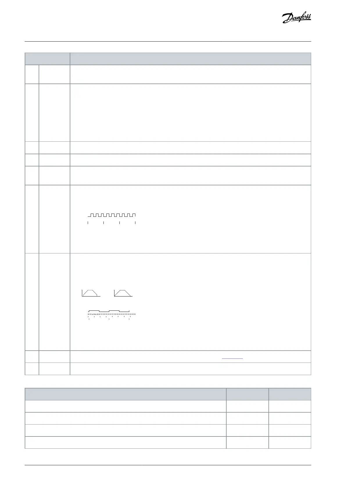
Counts the number of pulse flanks per sample time. This gives a higher resolution at high frequencies, but is
not as precise at lower frequencies. Use this pulse principle for encoders with low resolution (for example
30 PPR).
Pulse
Sample time
e30bb463.10
Illustration 61: Pulse Flanks per Sample Time
Measures the duration between pulse flanks. This gives a higher resolution at lower frequencies, but is not
as precise at higher frequencies. This principle has a cutoff frequency, which makes it unsuited for encoders
with low resolutions (for example 30 PPR) at low speeds.
Spee d [rpm] Spee d [rpm]
Read Timer:
20 timer tides
Read Timer:
20 timer tides
Time Start
Time counter
Illustration 62: Duration Between Pulse Flanks
Enables a selection between 1 of the 4 ramps available, according to Table 333.
Table 333: Preset Ramp Bit
AU275636650261en-000101 / 130R0334182 | Danfoss A/S © 2022.12
Parameter Descriptions
VLT AutomationDrive FC 301/302
Programming Guide

 Loading...


