5.13.3 13-2* Timers
Use the result (true or false) from timers directly to define an event (see parameter 13-51 SL Controller Event), or as boolean input in a
logic rule (see parameter 13-40 Logic Rule Boolean 1, parameter 13-42 Logic Rule Boolean 2, or parameter 13-44 Logic Rule Boolean 3). A
timer is only false when started by an action (for example [29] Start timer 1) until the timer value entered in this parameter has
elapsed. Then it becomes true again. All parameters in this parameter group are array parameters with index 0–9. Select index 0 to
program timer 0, select index 1 to program timer 1, and so on.
Parameter 13-20 SL Controller Time
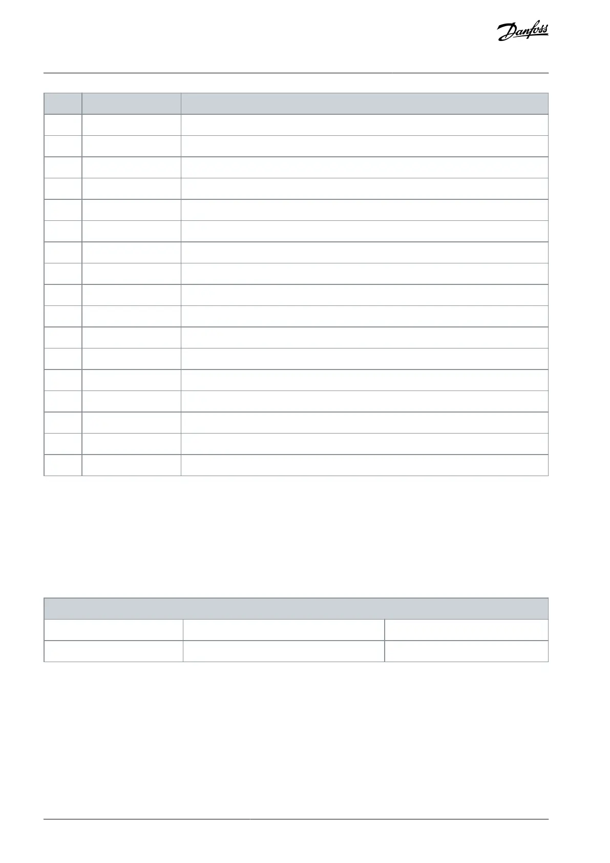
Table 680: Parameter 13-20 SL Controller Timer
13-20 SL Controller Timer
Default value: Size related
Parameter type: Range, 0 - 0, Array [10]
Data type: Timediff w/o DateID
Change during operation: True
Enter the value to define the duration of the false output from the programmed timer. A timer is only false if it is started by an action
(that is [29] Start timer 1) and until the given timer value has elapsed.
5.13.4 13-4* Logic Rules
Combine up to 3 boolean inputs (true/false inputs) from timers, comparators, digital inputs, status bits, and events using the logical
operators AND, OR, and NOT. Select boolean inputs for the calculation in parameter 13-40 Logic Rule Boolean 1, parameter 13-42 Logic
Rule Boolean 2, and parameter 13-44 Logic Rule Boolean 3. Define the operators used to logically combine the selected inputs in
parameter 13-41 Logic Rule Operator 1 and parameter 13-43 Logic Rule Operator 2.
AU275636650261en-000101 / 130R0334398 | Danfoss A/S © 2022.12
Parameter Descriptions
VLT AutomationDrive FC 301/302
Programming Guide

 Loading...


