The functions of the LEDs and switches on the front panel
are introduced in Table 5.14.
LED/Switch Description
NS2 Not used for PROFIBUS.
NS1 Indicates the network status when communi-
cating with the PROFIBUS master. When this
indicator light shows constant green, data
exchange between the master and the frequency
converter is active.
MS Indicates the module status, which is acyclic DP
V1 communication from either a PROFIBUS
master class 1 (PLC) or a master class 2 (MCT-10
Set-up Software, FDT tool). When this indicator
light shows constant green, DP V1 communi-
cation from master classes 1 and 2 is active.
COM Communication status for RS485. Not used for
PROFIBUS.
Termination
resistor
switch
When the switch is turned on, the termination
resistor is in eect.
PROFIBUS
address
selector
Use the switches in the selector to set the
PROFIBUS address. The address change comes
into eect at the next power-up.
NOTICE
Switch o the power supply before
changing the switches.
Table 5.14 Functions of LEDs and Switches
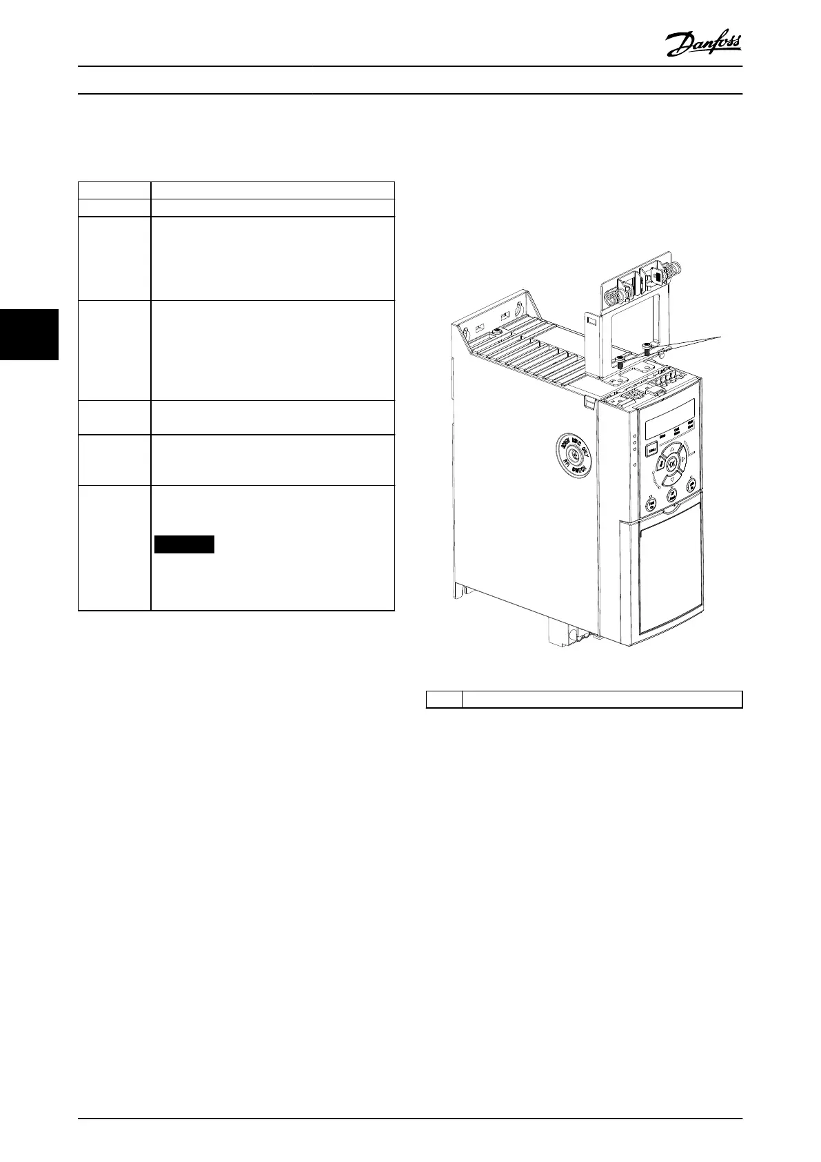
The PROFIBUS decoupling kit contains parts that are
required for PROFIBUS to work. Install the kit after the
control cassette with PROFIBUS is installed. Illustration 5.13
and Illustration 5.14 show how to install the decoupling kit
on a frequency converter.
1 Screws
Illustration 5.13 Fasten the Plate with Screws
Commissioning
VLT
®
AutomationDrive FC 360
34 Danfoss A/S © 03/2017 All rights reserved. MG06A702
55

 Loading...


