175ZA166.13
0,01 0,1 1 10 100 MHz
10
10
10
1
10
10
10
10
10
a
b
c
d
e
f
g
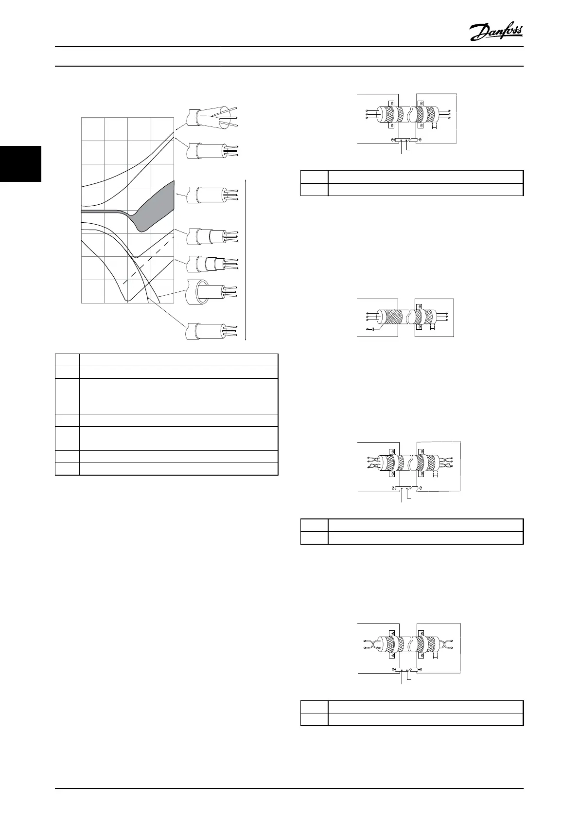
The lower the Z the better the cable screening performance
Transfer impedance, Z
t
mOhm/m
a Aluminium-clad with copper wire
b Twisted copper wire or armoured steel wire cable
c Single-layer braided copper wire with varying percentage
screen coverage (this is the typical Danfoss reference
cable).
d Double-layer braided copper wire
e Twin layer of braided copper wire with a magnetic,
screened/armoured intermediate layer
f Cable that runs in copper tube or steel tube
g Lead cable with 1.1 mm wall thickness
Illustration 3.54 Cable Screening Performance
3.5.3
Grounding of Screened Control
Cables
Correct screening
The preferred method in most cases is to secure control
and serial communication cables with screening clamps
provided at both ends to ensure best possible high
frequency cable contact. If the ground potential between
the frequency converter and the PLC is different, electric
noise may occur that disturbs the entire system. Solve this
problem by fitting an equalizing cable next to the control
cable. Minimum cable cross section: 16 mm
2
.
1
2
PE
FC
PE
PLC
130BB922.12
PE PE
<10 mm
1
Min. 16 mm
2
2 Equalizing cable
Illustration 3.55 Correct Screening
50/60 Hz ground loops
With very long control cables, ground loops may occur. To
eliminate ground loops, connect one end of the screen-to-
ground with a 100 nF capacitor (keeping leads short).
100nF
FC
PE
PE
PLC
<10 mm
130BB609.12
Illustration 3.56 Avoiding Ground Loops
Avoid EMC noise on serial communication
This terminal is connected to ground via an internal RC
link. Use twisted-pair cables to reduce interference
between conductors. The recommended method is shown
below:
PE
FC
PE
FC
130BB923.12
PE PE
69
68
61
69
68
61
1
2
<10 mm
1
Min. 16 mm
2
2 Equalizing cable
Illustration 3.57 Avoiding EMC Noise
Alternatively, the connection to terminal 61 can be
omitted:
PE
FC
PE
FC
130BB924.12
PE PE
69
69
68
68
1
2
<10 mm
1
Min. 16 mm
2
2 Equalizing cable
Illustration 3.58 Screening without Using Terminal 61
Installation Operating Instructions
50 Danfoss A/S © Rev. 05/2014 All rights reserved. MG16J202
33

 Loading...


