176FA246.10
U/T1 96
-DC 88
R/L1 91
S/L2 92
T/L3 93
+DC 89
V/T2 97
W/13
Illustration 3.61 Control Card Wiring Path for E-enclosures
In the Chassis (IP00) and NEMA 1 units, it is also possible
to connect the fieldbus from the top of the unit. On the
NEMA 1 unit, a cover plate must be removed.
Kit number for fieldbus top connection: 176F1742
3.5.6
Safe Torque Off (STO)
Safe Torque Off is an option. To run Safe Torque Off,
additional wiring for the frequency converter is required.
Refer to VLT
®
Frequency Converters Safe Torque Off
Operating Instructions for further information.
3.5.7
Control Terminal Functions
Frequency converter functions are commanded by
receiving control input signals.
•
Each terminal must be programmed for the
function it is supporting in the parameters
associated with that terminal. See
chapter 6 Programming and chapter 7 Application
Examples for terminals and associated parameters.
•
It is important to confirm that the control
terminal is programmed for the correct function.
See chapter 6 Programming for details on
accessing parameters and programming.
•
The default terminal programming is intended to
initiate frequency converter functioning in a
typical operational mode.
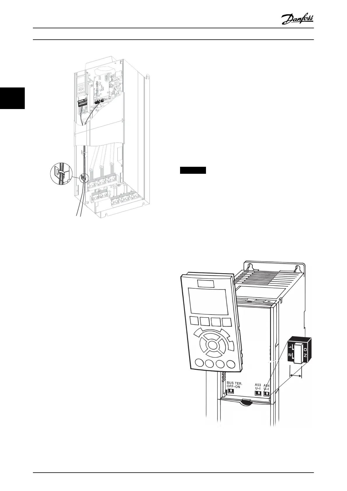
3.5.7.1 Terminal 53 and 54 Switches
•
Analog input terminals 53 and 54 can select
either voltage (0 to 10 V) or current (0/4-20 mA)
input signals.
•
Remove power to the frequency converter before
changing switch positions.
•
Set switches A53 and A54 to select the signal
type. U selects voltage, I selects current.
•
The switches are accessible when the LCP has
been removed (see Illustration 3.62).
NOTICE
Some option cards available for the unit may cover these
switches and must be removed to change switch
settings. Always remove power to the unit before
removing option cards. Observe the discharge time in
Table 2.1.
•
Terminal 53 default is for a speed reference signal
in open loop, which is set in 16-61 Terminal 53
Switch Setting
•
Terminal 54 default is for a feedback signal in
closed loop, which is set in 16-63 Terminal 54
Switch Setting
Illustration 3.62 Location of Terminals 53 and 54 Switches and
Bus Termination Switch
Installation Operating Instructions
52 Danfoss A/S © Rev. 05/2014 All rights reserved. MG16J202
33
 Loading...


