9.4 Warning and Alarm Definitions
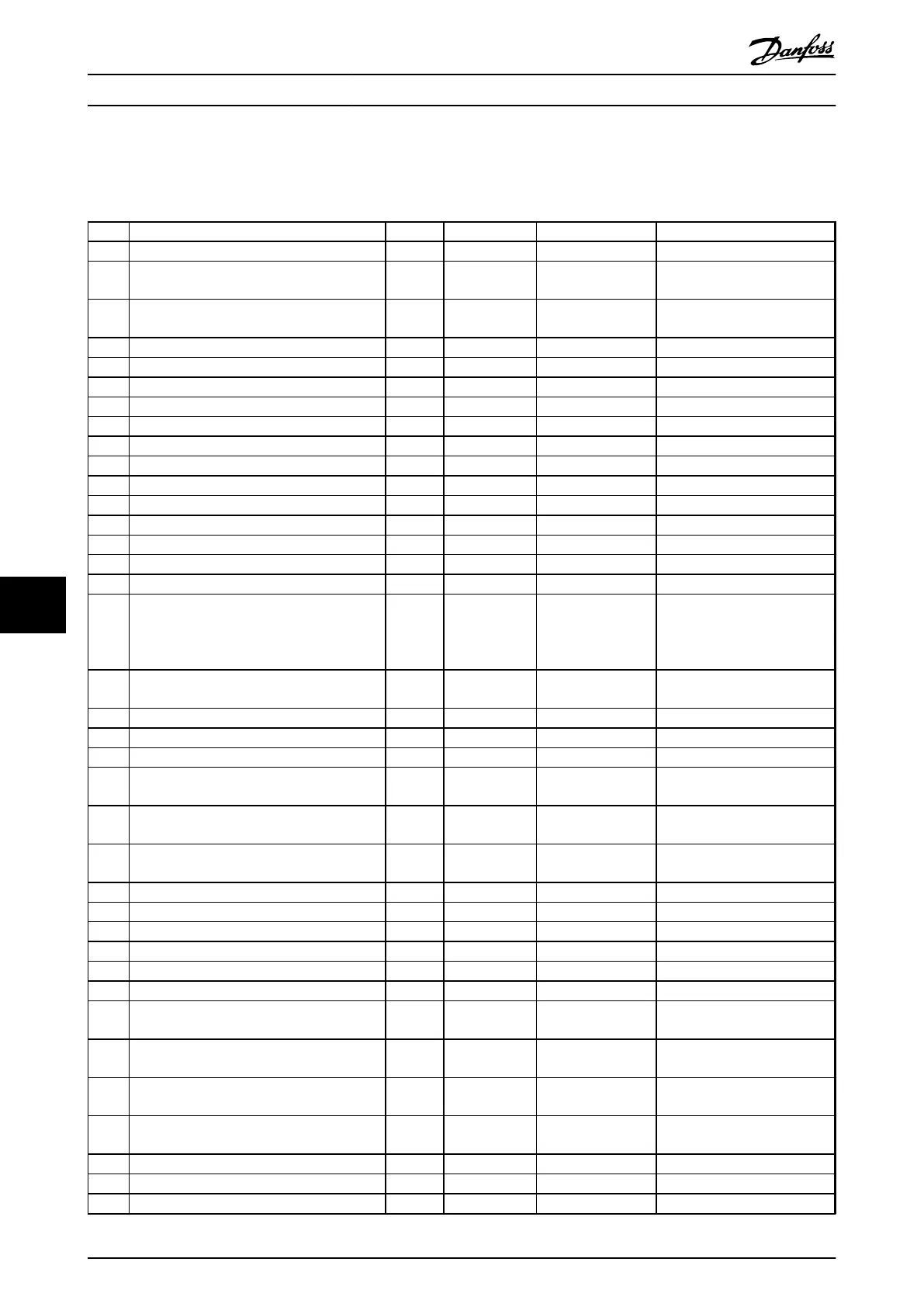
Table 9.1 defines whether a warning is issued before an alarm, and whether the alarm trips the unit or trip locks the unit.
No. Description Warning Alarm/Trip Alarm/Trip lock Parameter reference
1 10 Volts low X
2 Live zero error (X) (X) 6-01 Live Zero Timeout
Function
4 Mains phase loss (X) (X) (X) 14-12 Function at Mains
Imbalance
5 DC link voltage high X
6 DC link voltage low X
7 DC over voltage X X
8 DC under voltage X X
9 Inverter overloaded X X
10 Motor ETR over temperature (X) (X) 1-90 Motor Thermal Protection
11 Motor thermistor over temperature (X) (X) 1-90 Motor Thermal Protection
12 Torque limit X X
13 Over Current X X X
14 Earth (ground) fault X X X
15 Hardware mismatch X X
16 Short Circuit X X
17 Control word timeout (X) (X) 8-04 Control Timeout Function
18 Start Failed X
1-77 Compressor Start Max
Speed [RPM],
1-79 Pump Start Max Time to
Trip
19 Discharge Temperature High X
28-25 Warning Action
28-26 Emergency Level
23 Internal Fan Fault X
24 External Fan Fault X 14-53 Fan Monitor
29 Drive over temperature X X X
30 Motor phase U missing (X) (X) (X) 4-58 Missing Motor Phase
Function
31 Motor phase V missing (X) (X) (X) 4-58 Missing Motor Phase
Function
32 Motor phase W missing (X) (X) (X) 4-58 Missing Motor Phase
Function
33 Inrush fault X X
34 Fieldbus communication fault X X
35 Out of frequency range X X
36 Mains failure X X
38 Internal fault X X
39 Heatsink sensor X X
40 Overload of Digital Output Terminal 27 (X) 5-00 Digital I/O Mode,
5-01 Terminal 27 Mode
41 Overload of Digital Output Terminal 29 (X) 5-00 Digital I/O Mode,
5-02 Terminal 29 Mode
42 Overload of Digital Output On X30/6 (X) 5-32 Term X30/6 Digi Out (MCB
101)
42 Overload of Digital Output On X30/7 (X) 5-33 Term X30/7 Digi Out (MCB
101)
46 Pwr. card supply X X
47 24 V supply low X X X
48 1.8 V supply low X X
Warnings and Alarms Operating Instructions
84 Danfoss A/S © Rev. 05/2014 All rights reserved. MG16J202
99

 Loading...


