1.6 Internal Controller Functions
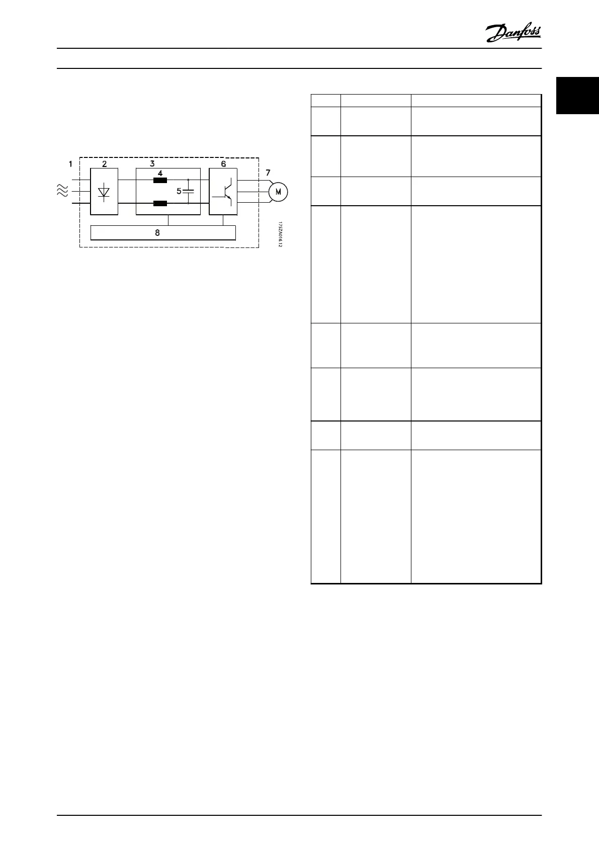
Illustration 1.5 is a block diagram of the frequency
converter's internal components.
Illustration 1.5 Frequency Converter Block Diagram
Area Title Functions
1 Mains input
•
3-phase AC mains supply to the
frequency converter
2 Rectifier
•
The rectifier bridge converts the
AC input to DC current to
supply inverter power.
3 DC-bus
•
Intermediate DC-bus circuit
handles the DC current.
4 DC reactors
•
Filter the intermediate DC circuit
voltage.
•
Prove line transient protection.
•
Reduce RMS current.
•
Raise the power factor reflected
back to the line.
•
Reduce harmonics on the AC
input.
5 Capacitor bank
•
Stores the DC power.
•
Provides ride-through protection
for short power losses.
6 Inverter
•
Converts the DC into a
controlled PWM AC waveform
for a controlled variable output
to the motor.
7 Output to motor
•
Regulated 3-phase output
power to the motor
8 Control circuitry
•
Input power, internal
processing, output, and motor
current are monitored to
provide efficient operation and
control.
•
User interface and external
commands are monitored and
performed.
•
Status output and control can
be provided.
Table 1.2 Legend to Illustration 1.5
Introduction Operating Instructions
MG16J202 Danfoss A/S © Rev. 05/2014 All rights reserved. 7
1
1

 Loading...


