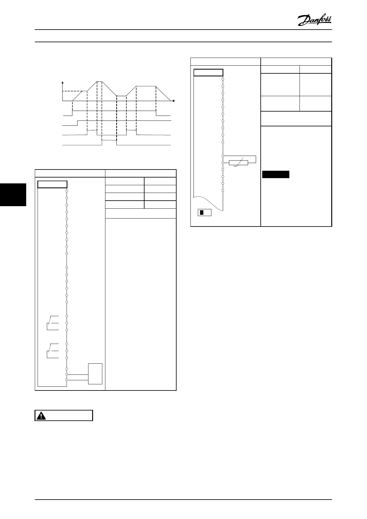
S t a r t ( 1 8 )
F r e e z e r e f ( 2 7 )
S p e e d u p ( 2 9 )
S p e e d d o w n ( 3 2 )
S p e e d
R e f e r e n c e
130BB840.10
Illustration 7.3 Speed Up/Down
Parameters
FC
+24 V
+24 V
D IN
D IN
D IN
COM
D IN
D IN
D IN
D IN
+10
A IN
A IN
COM
A OUT
COM
R1R2
12
13
18
19
20
27
29
32
33
37
50
53
54
55
42
39
01
02
03
04
05
06
-
61
68
69
RS-485
+
130BB685.10
Function Setting
8-30 Protocol
FC*
8-31 Address
1*
8-32 Baud Rate
9600*
* = Default Value
Notes/comments:
Select protocol, address and
baud rate in the above
mentioned parameters.
D IN 37 is an option.
Table 7.11 RS-485 Network Connection
CAUTION
Thermistors must use reinforced or double insulation to
meet PELV insulation requirements.
Parameters
130BB686.12
VLT
+24 V
+24 V
D IN
D IN
D IN
COM
D IN
D IN
D IN
+10 V
A IN
A IN
COM
A OUT
COM
12
13
18
19
20
27
29
32
33
50
53
54
55
42
39
A53
U - I
D IN
37
Function Setting
1-90 Motor
Thermal
Protection
[2]
Thermistor
trip
1-93 Thermistor
Source
[1] Analog
input 53
* = Default Value
Notes/comments:
If only a warning is desired,
1-90 Motor Thermal Protection
should be set to [1] Thermistor
warning.
D IN 37 is an option.
NOTICE
Danfoss recommends using
24 V DC as thermistor
supply voltage.
Table 7.12 Motor Thermistor
Application Examples Operating Instructions
80 Danfoss A/S © Rev. 05/2014 All rights reserved. MG16J202
77

 Loading...


