90
80
70
60
50
40
30
20
10
0
(%)
Drive Derating
0 25 50 75 100 125 150 175 225
130BB190.10
200
Pressure Change
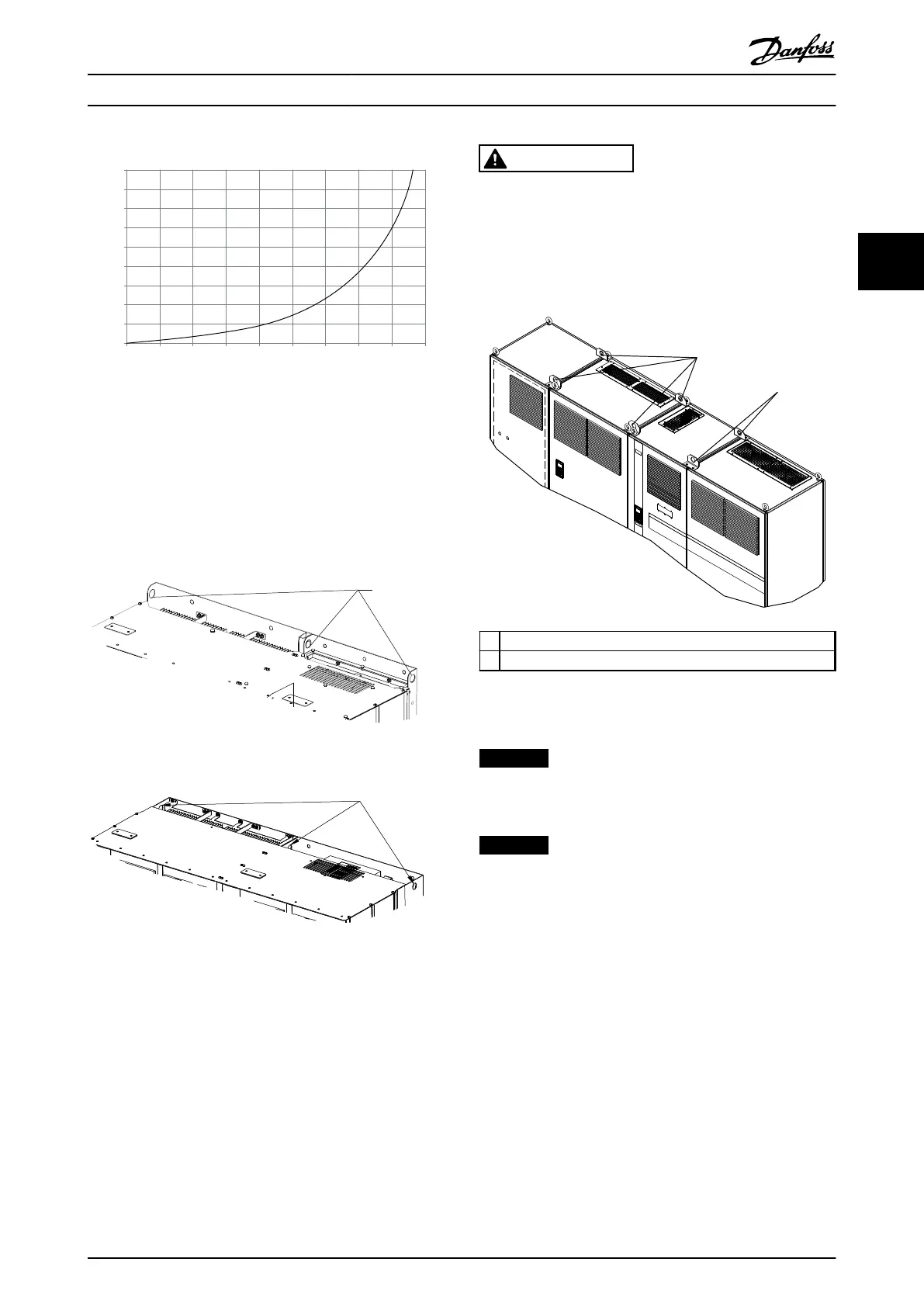
Illustration 3.4 F-Frame Derating vs. Pressure Change
Drive Air Flow: 580 cfm (985 m
3
/h)
3.3.2
Lifting
Lift the frequency converter using the dedicated lifting
eyes. For all D-frames, use a bar to avoid bending the
lifting holes of the frequency converter.
Illustration 3.5 Recommended Lifting Method, Frame Size D13
Illustration 3.6 Recommended Lifting Method, Frame Size E9
WARNING
The lifting bar must be able to handle the weight of the
frequency converter. See chapter 11.2 Mechanical
Dimensions for the weight of the different frame sizes.
Maximum diameter for bar is 2.5 cm (1 inch). The angle
from the top of the frequency converter to the lifting
cable should be 60° or greater.
1 Lifting holes for the filter
2 Lifting holes for the frequency converter
Illustration 3.7 Recommended Lifting Method, Frame Size F18
NOTICE
A spreader bar is also an acceptable way to lift the F-
frame.
NOTICE
The F18 pedestal is packaged separately and included in
the shipment. Mount the frequency converter on the
pedestal in its final location. The pedestal allows proper
airflow and cooling.
Installation Operating Instructions
MG37A202 Danfoss A/S © Rev. 2014-07-29 All rights reserved. 17
3 3

 Loading...


