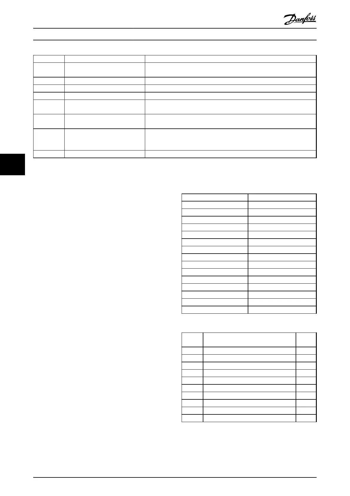
Group Title Function
0-** Operation/Display Parameters related to the fundamental functions of the filter, function of the LCP
buttons and configuration of the LCP display.
5-** Digital In/Out Parameter group for configuring the digital inputs and outputs.
8-** Communication and Options Parameter group for configuring communications and options.
14-** Special Functions Parameter group for configuring special functions.
15-** Unit Information Parameter group containing active filter information such as operating data,
hardware configuration and software versions.
16-** Data Readouts Parameter group for data read-outs, e.g. actual references, voltages, control, alarm,
warning and status words.
300-** AF Settings
Parameter group for setting the Active Filter. Apart from par. 300-10, Active Filter
Nominal Voltage, it is not recommended to change the settings of this parameter
group
301-** AF Readouts Parameter group for the filter readouts.
Table 6.10 Parameter Groups
A list of all parameters accessible from the filter LCP can be found in the section Parameter Options - Filter. A more detailed
description of the active filter parameters can be found in chapter 6.4 Parameter Lists - Active Filter.
6.2.1
Using the Low Harmonic Drive in NPN
Mode
The default setting for parameter 5-00 Digital I/O Mode is
PNP mode. If NPN mode is desired, it is necessary to
change the wiring in the filter part of the Low Harmonic
Drive. Before changing the setting in parameter 5-00 Digital
I/O Mode to NPN mode, the wire connected to 24 V
(control terminal 12 or 13) must be changed to terminal 20
(ground).
6.3 Parameter Lists - Frequency Converter
Changes during operation
True means that the parameter can be changed while the
frequency converter is in operation and false means that it
must be stopped before making a change.
4-Set-up
'All set-up': the parameters can be set individually in each
of the 4 set-ups, i.e. one single parameter can have four
different data values.
’1 set-up’: data value is the same in all set-ups.
Conversion index
This number refers to a conversion figure used when
writing or reading to and from the frequency converter.
Conv. index Conv. factor
100 1
67 1/60
6 1000000
5 100000
4 10000
3 1000
2 100
1 10
0 1
-1 0.1
-2 0.01
-3 0.001
-4 0.0001
-5 0.00001
-6 0.000001
Table 6.11 Conversion Index
Data
type
Description Type
2 Integer 8 Int8
3 Integer 16 Int16
4 Integer 32 Int32
5 Unsigned 8 Uint8
6 Unsigned 16 Uint16
7 Unsigned 32 Uint32
9 Visible String VisStr
33 Normalized value 2 bytes N2
35 Bit sequence of 16 boolean variables V2
54 Time difference w/o date TimD
Table 6.12 Data Types
See the frequency converter Design Guide for further
information about data types 33, 35 and 54.
Programming Operating Instructions
72 Danfoss A/S © Rev. 2014-07-29 All rights reserved. MG37A202
66

 Loading...


