Frame size Terminal Torque Bolt size
D
Mains
Motor
19–40 Nm
(168–354 in-lbs)
M10
Load sharing
Brake
8.5–20.5 Nm
(75–181 in-lbs)
M8
E
Mains
Motor
Load sharing
19–40 Nm
(168–354 in-lbs)
M10
Brake
8.5–20.5 Nm
(75–181 in-lbs)
M8
F
Mains
Motor
19–40 Nm
(168–354 in-lbs)
M10
Load sharing
19–40 Nm
(168–354 in-lbs)
M10
Brake
8.5–20.5 Nm
(75–181 in-lbs)
M8
Regen
8.5–20.5 Nm
(75–181 in-lbs)
M8
Table 3.14 Torque for terminals
3.6 Additional Connections
3.6.1 Mechanical Brake Control
In hoisting/lowering applications, it is necessary to be
able to control an electro-mechanical brake:
•
Control the brake using any relay output or
digital output (terminal 27 or 29).
•
Keep the output closed (voltage-free) as long as
the frequency converter is unable to ‘support’ the
motor, due to the load being too heavy, for
example.
•
Select [32] Mechanical brake control in parameter
group 5-4* Relays for applications with an electro-
mechanical brake.
•
The brake is released when the motor current
exceeds the preset value in
parameter 2-20 Release Brake Current.
•
The brake engages when the output frequency is
less than the frequency set in
parameter 2-21 Activate Brake Speed [RPM] or
parameter 2-22 Activate Brake Speed [Hz], only if
the frequency converter completes a stop
command.
If the frequency converter is in alarm mode or in an
overvoltage situation, the mechanical brake immediately
cuts in.
3.6.2
Parallel Connection of Motors
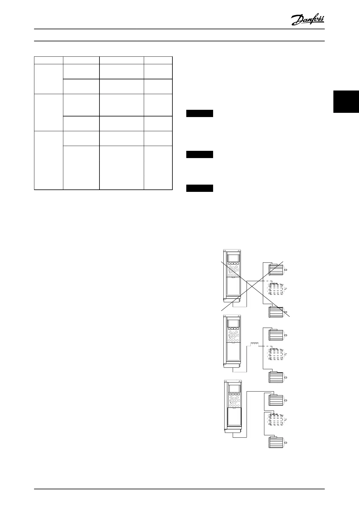
The frequency converter can control several parallel-
connected motors. The total current consumption of the
motors must not exceed the rated output current I
M,N
for
the frequency converter.
NOTICE
Installations with cables connected in a common joint as
in Illustration 3.31, is only recommended for short cable
lengths.
NOTICE
When motors are connected in parallel, 1-29 Automatic
Motor Adaptation (AMA) cannot be used.
NOTICE
The electronic thermal relay (ETR) of the frequency
converter cannot be used as motor protection for the
individual motor in systems with parallel-connected
motors. Provide further motor protection with
thermistors in each motor or individual thermal relays.
Circuit breakers are not suitable as protection.
Illustration 3.31 Installations with Cables Connected in a
Common Joint
Installation Operating Instructions
MG37A202 Danfoss A/S © Rev. 2014-07-29 All rights reserved. 35
3 3

 Loading...


