If found to be necessary and after consultation with
Danfoss:
•
Lower the IGBT switching frequency
•
Modify the inverter waveform, 60° AVM vs.
SFAVM
•
Install a shaft grounding system or use an
isolating coupling between motor and load
•
Use minimum speed settings if possible
•
Use a dU/dt or sine-wave filter
3.4.16 Motor Thermal Protection
The electronic thermal relay in the frequency converter has
received UL-approval for single motor protection, when
parameter 1-90 Motor Thermal Protection is set for ETR Trip
and 1-24 Motor Current is set to the rated motor current
(see the motor name plate).
For thermal motor protection, it is also possible to use the
MCB 112 PTC Thermistor Card option. This card provides
ATEX certificate to protect motors in explosion hazardous
areas, Zone 1/21 and Zone 2/22. When
parameter 1-90 Motor Thermal Protection, set to [20] ATEX
ETR, is combined with the use of MCB 112, it is possible to
control an Ex-e motor in explosion hazardous areas.
Consult the Programming Guide for details on how to set
up the frequency converter for safe operation of Ex-e
motors.
To run STO, additional wiring for the frequency converter
is required. Refer to VLT
®
Frequency Converters Safe Torque
Off Operating Instructions for further information.
3.4.17
Control Cable Routing
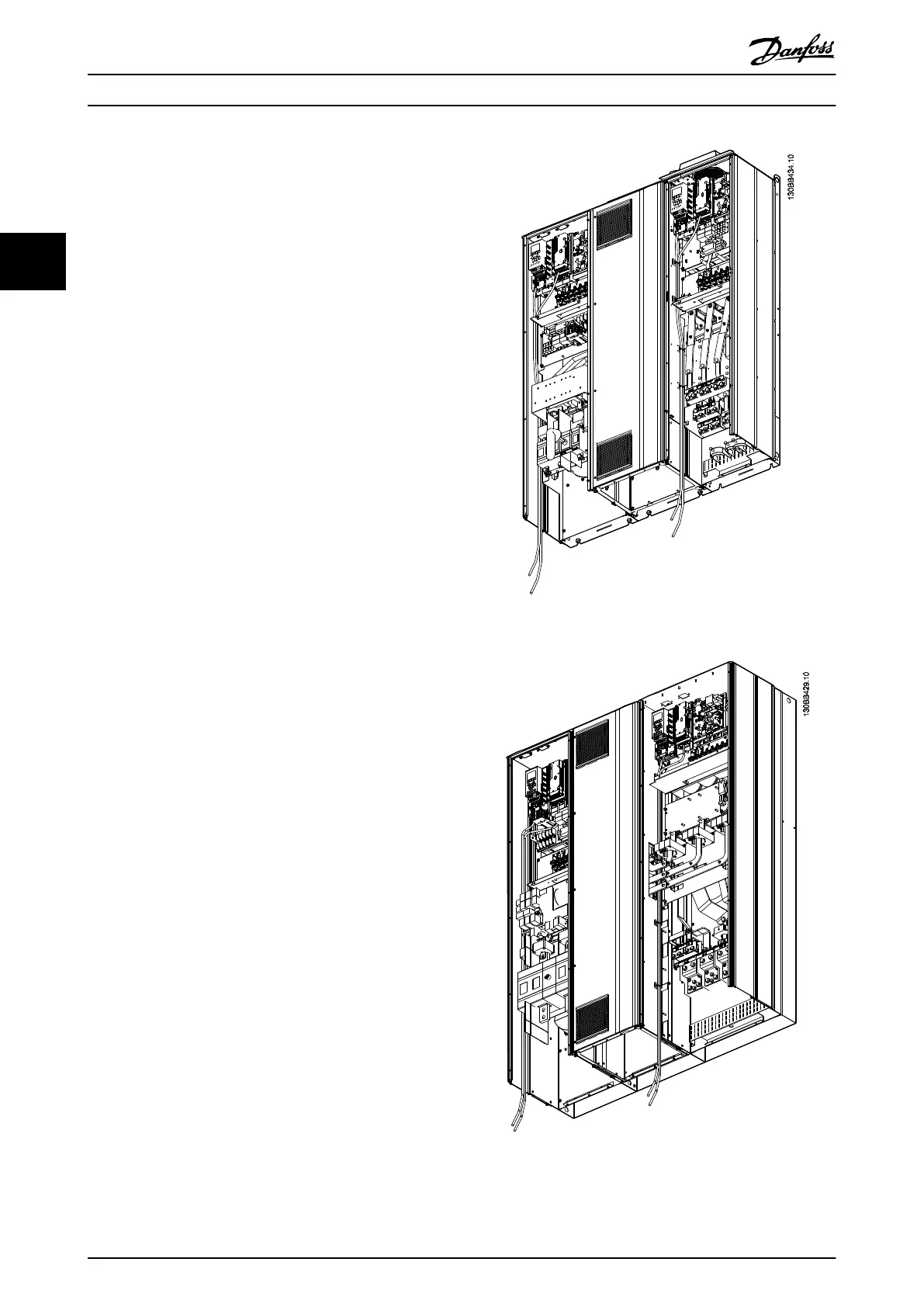
Tie down all control wires to the designated control cable
routing as shown in Illustration 3.21, Illustration 3.22, and
Illustration 3.23. Remember to connect the shields in a
proper way to ensure optimum electrical immunity.
Fieldbus connection
Connections are made to the relevant options on the
control card. For details, see the relevant fieldbus
instruction. The cable must be placed in the provided path
inside the frequency converter and tied down together
with other control wires (see Illustration 3.21 and
Illustration 3.22).
Illustration 3.21 Control Card Wiring Path for Frame Size D13
Illustration 3.22 Control Card Wiring Path for Frame Size E9
Installation Operating Instructions
30 Danfoss A/S © Rev. 2014-07-29 All rights reserved. MG37A202
33

 Loading...


