3.4.2 Extra Protection (RCD)
ELCB relays, multiple protective grounding, or standard
grounding provide extra protection, if local safety
regulations are followed.
In the case of a ground fault, a DC component develops in
the fault current.
If using ELCB relays, observe local regulations. Relays must
be suitable for protection of 3-phase equipment with a
bridge rectifier and for a brief discharge on power-up.
3.4.3
RFI Switch
Mains supply isolated from ground
If the frequency converter is supplied from an isolated
mains source or TT/TN-S mains with grounded leg, turn off
the RFI switch via 14-50 RFI Filter on both frequency
converter and the filter. For further reference, see IEC
364-3. When optimum EMC performance is needed,
parallel motors are connected, or the motor cable length is
above 25 m, set 14-50 RFI Filter to [ON].
In OFF, the internal RFI capacitors (filter capacitors)
between the chassis and the intermediate circuit are cut
off to avoid damage to the intermediate circuit and reduce
ground capacity currents (IEC 61800-3).
Refer to the application note VLT on IT mains. It is
important to use isolation monitors that work together
with power electronics (IEC 61557-8).
3.4.4
Shielded Cables
It is important to connect shielded cables properly to
ensure high EMC immunity and low emissions.
Connection can be made using either cable glands or
clamps:
•
EMC cable glands: Generally available cable
glands can be used to ensure an optimum EMC
connection.
•
EMC cable clamp: Clamps allowing easy
connection are supplied with the unit.
3.4.5
Motor Cable
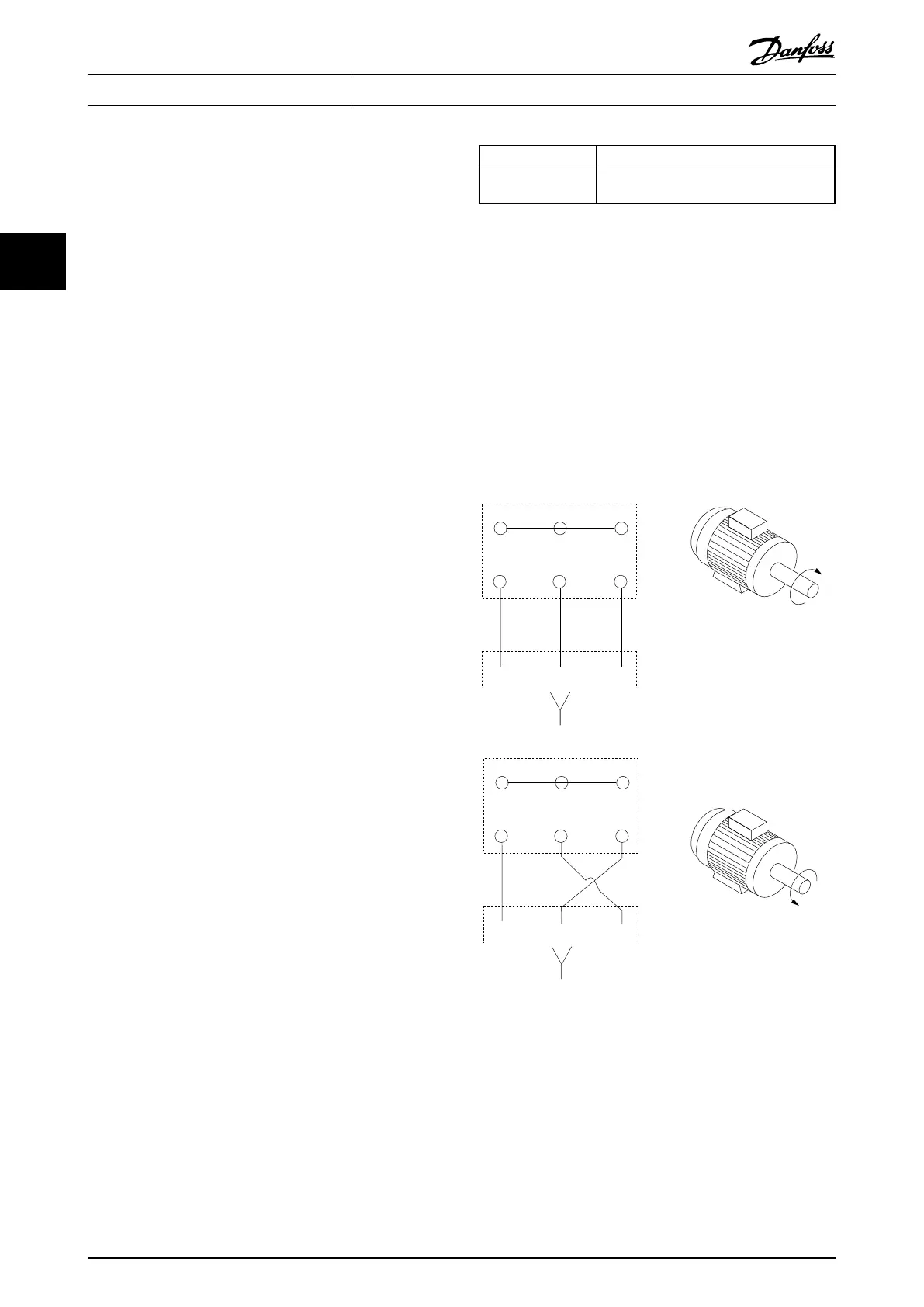
Connect the motor to terminals U/T1/96, V/T2/97, W/T3/98,
on the far right of the unit. Ground to terminal 99. All
types of 3-phase asynchronous standard motors can be
used with a frequency converter. The factory setting is for
clockwise rotation with the frequency converter output
connected as follows:
Terminal No. Function
96, 97, 98
99
Mains U/T1, V/T2, W/T3
Ground
Table 3.4 Terminal Functions
•
Terminal U/T1/96 connected to U-phase
•
Terminal V/T2/97 connected to V-phase
•
Terminal W/T3/98 connected to W-phase
The direction of rotation can be changed by switching 2
phases in the motor cable or by changing the setting of
4-10 Motor Speed Direction.
Motor rotation check can be performed via 1-28 Motor
Rotation Check and following the steps shown in the
display.
175HA036.11
U
1
V
1
W
1
96 97 98
FC
Motor
U
2
V
2
W
2
U
1
V
1
W
1
96 97 98
FC
Motor
U
2
V
2
W
2
Illustration 3.18 Motor Rotation Check
F-frame requirements
Use motor phase cables in quantities of 2, resulting in 2, 4,
6, or 8 to obtain an equal number of wires on both
inverter module terminals. The cables are required to be
equal length within 10% between the inverter module
terminals and the first common point of a phase. The
recommended common point is the motor terminals.
Installation
Operating Instructions
26 Danfoss A/S © Rev. 2014-07-29 All rights reserved. MG37A202
33

 Loading...


