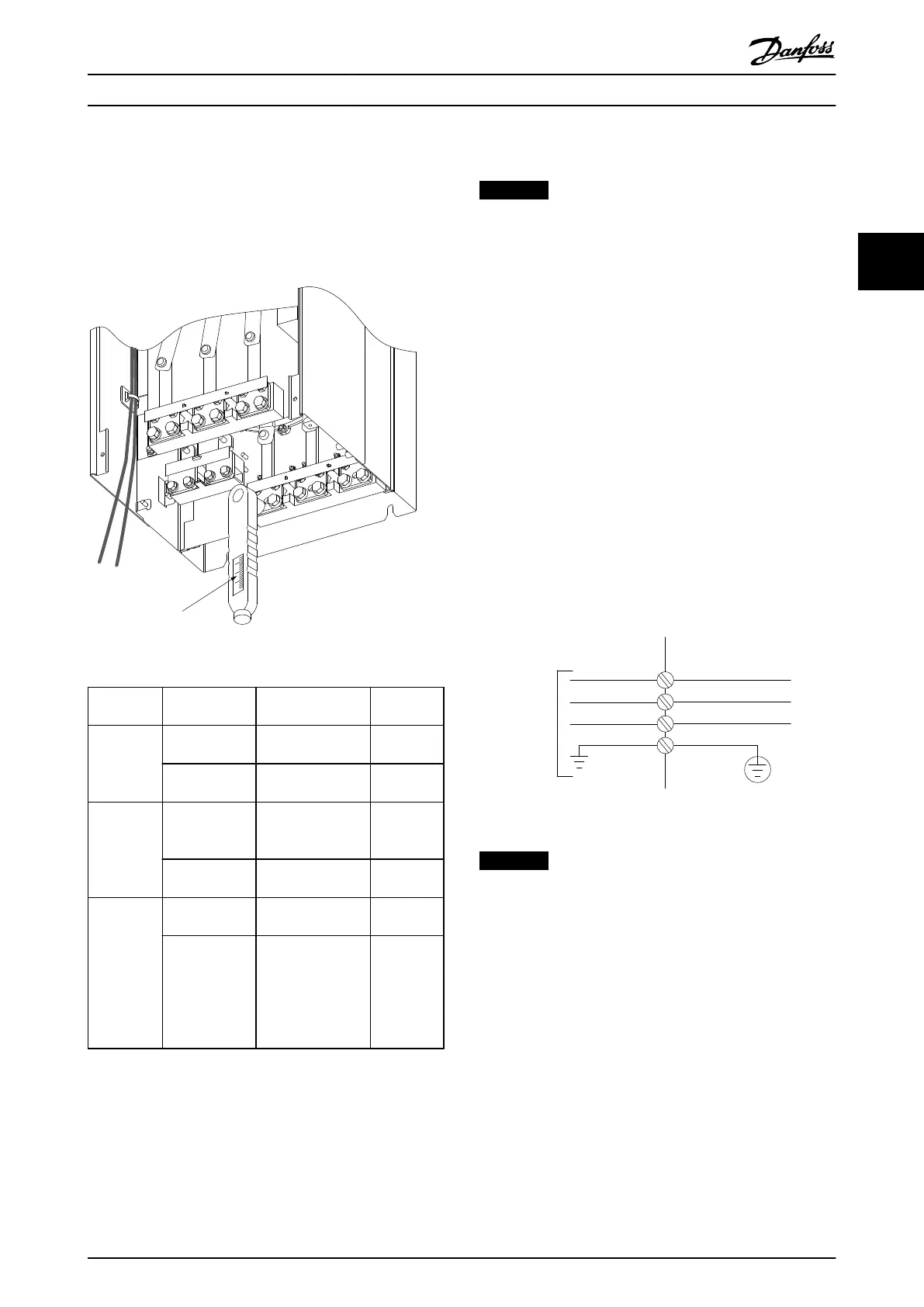
3.3.6 Torque
Correct torque is imperative for all electrical connections.
The correct torque values are listed in Table 3.2. Incorrect
torque results in a bad electrical connection. Use a torque
wrench to ensure correct torque.
176FA247.12
Nm/in-lbs
-DC 88
+DC 89
R/L1 91
S/L2 92
T/L3 93
U/T1 96
V/T2 97
W/T3
Illustration 3.14 Use a Torque Wrench to Tighten the Bolts
Frame size Terminal Torque [Nm] (in-
lbs)
Bolt size
D
Mains
Motor
19–40
(168–354)
M10
Load sharing
Brake
8.5–20.5
(75–181)
M8
E
Mains
Motor
Load sharing
19–40
(168–354)
M10
Brake
8.5–20.5
(75–181)
M8
F
Mains
Motor
19–40
(168–354)
M10
Load sharing
19–40
(168–354)
M10
Brake
8.5–20.5
(75–181)
M8
Regen
8.5–20.5
(75–181)
M8
Table 3.2 Torque for Terminals
3.4
Electrical Installation
NOTICE
Cables–General Information
All cabling must comply with national and local
regulations on cable cross-sections and ambient
temperature. UL applications require 75 °C copper
conductors. For non-UL applications, 75 and 90 °C
copper conductors are thermally acceptable.
The power cable connections are situated as shown in
Illustration 3.15. Dimension cable cross-section in
accordance with the current ratings and local legislation.
See chapter 11.3.1 Cable lengths and cross-sections for
details.
For protection of the frequency converter, use the
recommended fuses if there are no built-in fuses. Fuse
recommendations are provided in chapter 11.5 Fuses.
Ensure that proper fusing is made according to local
regulation.
The mains connection is fitted to the mains switch, if
included.
3 Phase
power
input
130BA026.10
91 (L1)
92 (L2)
93 (L3)
95 PE
Illustration 3.15 Power Cable Connections
NOTICE
To comply with EMC emission specifications, screened/
armoured cables are recommended. If an unscreened/
unarmoured cable is used, see chapter 3.4.10 Power and
Control Wiring for Unscreened Cables.
See chapter 11 Specifications for correct dimensioning of
motor cable cross-section and length.
Screening of cables
Avoid installation with twisted screen ends (pigtails). They
spoil the screening effect at higher frequencies. If breaking
the screen is necessary to install a motor isolator or
contactor, continue the screen at the lowest possible HF
impedance.
Connect the motor cable screen to both the de-coupling
plate of the frequency converter and to the metal housing
of the motor.
Installation
Operating Instructions
MG37A202 Danfoss A/S © Rev. 2014-07-29 All rights reserved. 23
3 3

 Loading...


