Output junction box requirements
The length, minimum 2.5 m, and quantity of cables must
be equal from each inverter module to the common
terminal in the junction box.
NOTICE
If a retrofit application requires an unequal number of
wires per phase, consult the factory or use the top/
bottom entry side cabinet option, instruction 177R0097.
3.4.6 Brake Cable
Frequency converters with factory installed brake chopper
option
(Only standard with letter B in position 18 of type code).
The connection cable to the brake resistor must be
screened and the max. length from frequency converter to
the DC bar is limited to 25 m.
Terminal No. Function
81, 82 Brake resistor terminals
Table 3.5 Terminal Functions
The connection cable to the brake resistor must be
screened. Connect the screen with cable clamps to the
conductive back plate of the frequency converter and the
metal cabinet of the brake resistor.
Size the brake cable cross-section to match the brake
torque.
WARNING
Note that voltages up to 790 V DC, depending on the
supply voltage, are possible on the terminals.
F-frame requirements
The brake resistors must be connected to the brake
terminals in each inverter module.
3.4.7
Brake Resistor Temperature Switch
The input for the brake resistor temperature switch can be
used to monitor the temperature of an externally
connected brake resistor. If the connection between 104
and 106 is removed, the frequency converter trips on
warning/alarm 27, Brake IGBT.
Install a Klixon switch that is 'normally closed' in series
with the existing connection on either 106 or 104. Any
connection to this terminal must be double insulated
against high voltage to maintain PELV.
Normally closed: 104–106 (factory installed jumper).
Terminal No. Function
106, 104, 105 Brake resistor temperature switch.
Table 3.6 Terminal Functions
CAUTION
If the temperature of the brake resistor is too high and
the thermal switch drops out, the frequency converter
stops braking. The motor coasts.
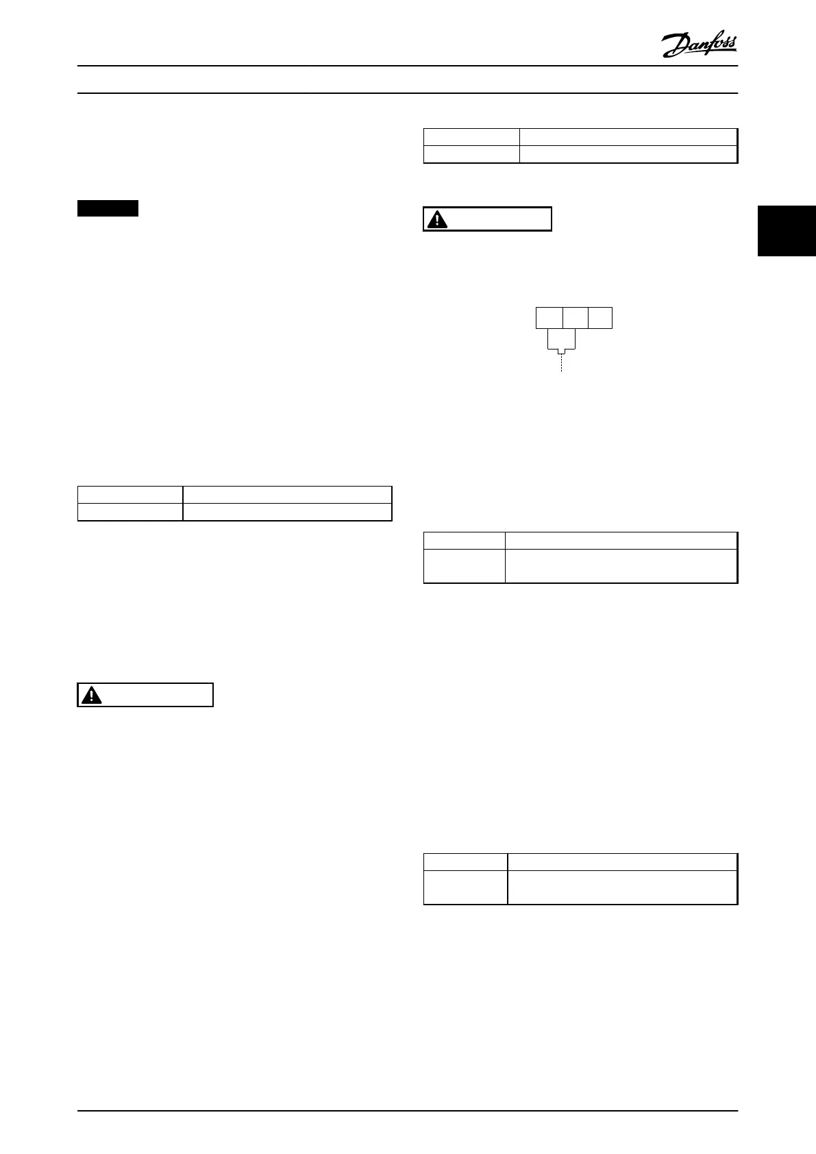
175ZA877.10
106
NC
104
C
105
NO
Illustration 3.19 Factory-installed Jumper
3.4.8 Mains Connection
Mains must be connected to terminals 91, 92 and 93 on
the far left of the unit. Ground is connected to the
terminal on the right of terminal 93.
Terminal No. Function
91, 92, 93
94
Mains R/L1, S/L2, T/L3
Ground
Table 3.7 Terminal Functions
Ensure that the power supply can supply the necessary
current to the frequency converter.
If the unit is without built-in fuses, ensure that the
appropriate fuses have the correct current rating.
3.4.9
External Fan Supply
If the frequency converter is supplied by DC or the fan
must run independently of the power supply, use an
external power supply. Make the connection on the power
card.
Terminal No. Function
100, 101
102, 103
Auxiliary supply S, T
Internal supply S, T
Table 3.8 Terminal Functions
The connector on the power card provides the connection
of line voltage for the cooling fans. The fans are connected
from the factory to be supplied from a common AC line
(jumpers between 100–102 and 101–103). If external
power supply is needed, remove the jumpers and connect
the supply to terminals 100 and 101. Protect with a 5 A
fuse. In UL applications, use a LittelFuse KLK-5 or
equivalent.
Installation
Operating Instructions
MG37A202 Danfoss A/S © Rev. 2014-07-29 All rights reserved. 27
3 3

 Loading...


