6.1.3 2-2* Mechanical Brake
Controlling operation of an electro-magnetic (mechanical) brake, typically required in hoisting applications requires special
parameters.
To control a mechanical brake, a relay output (relay 01 or relay 02) or a programmed digital output (terminal 27 or 29) is
required. Normally, this output must be closed during periods when the frequency converter is unable to ‘hold’ the motor,
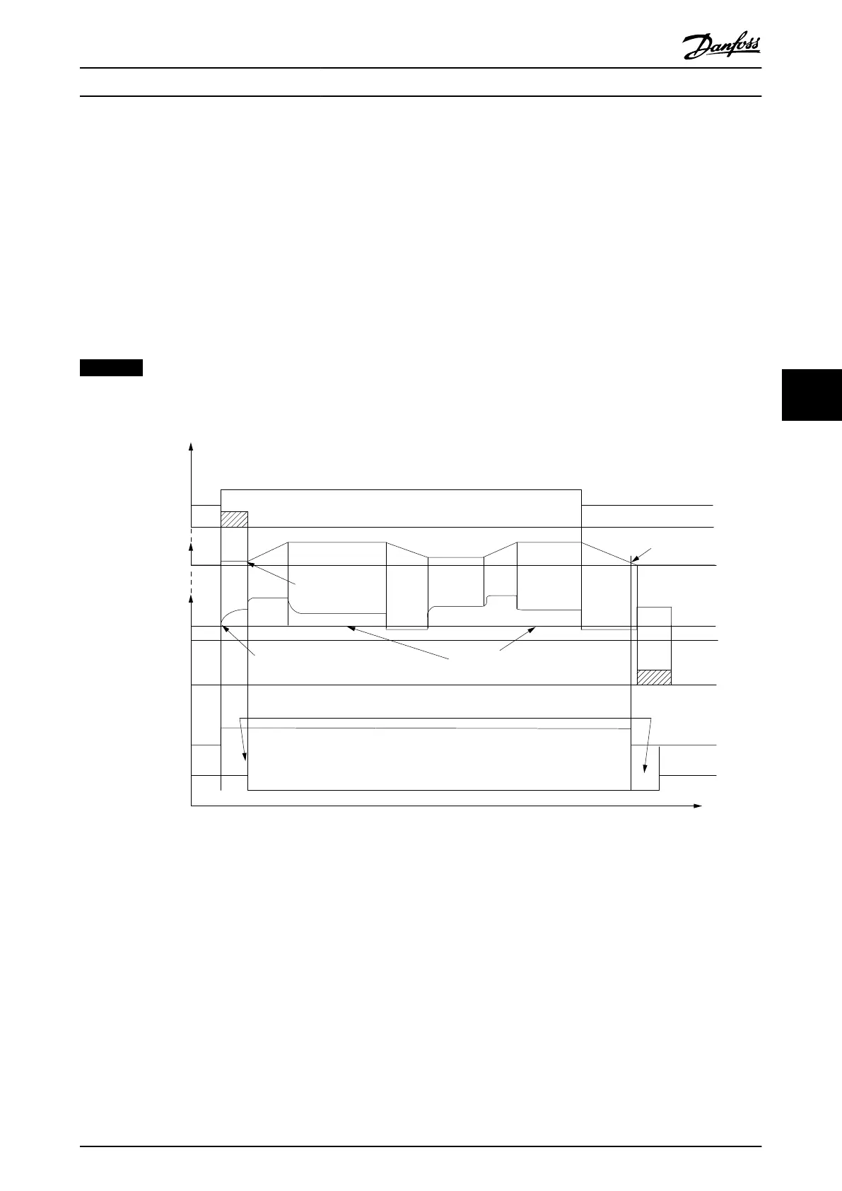
due to an excessive load. Select [32] Mechanical Brake Control for applications with an electro-magnetic brake in
parameter 5-40 Function Relay, 5-30 Terminal 27 Digital Output, or 5-31 Terminal 29 Digital Output. When selecting [32]
Mechanical brake control, the mechanical brake is closed from startup until the output current is above the level selected in
parameter 2-20 Release Brake Current. During stop, the mechanical brake activates when the speed falls below the level
specified in parameter 2-21 Activate Brake Speed [RPM]. If the frequency converter enters an alarm condition or an over-
current or overvoltage situation, the mechanical brake immediately cuts in, as in the Safe Torque Off function.
NOTICE
Protection mode and trip delay features (14-25 Trip Delay at Torque Limit and 14-26 Trip Delay at Inverter Fault) can
delay the activation of the mechanical brake in an alarm condition. Disable these features in hoisting applications.
Start
term.18
1=on
0=o
Shaft speed
Start delay time
on
o
Brake delay time
Time
Output current
Relay 01
Pre-magnetizing
current or
DC hold current
Reaction time EMK brake
Par 2-20
Release brake current
Par 1-76 Start current/
Par 2-00 DC hold current
Par 1-74
Start speed
Par 2-21
Activate brake
speed
Mechanical brake
locked
Mechanical brake
free
Par 1-71
Par 2-23
130BA074.12
Illustration 6.7 Mechanical Brake Function
Programming Operating Instructions
MG37A202 Danfoss A/S © Rev. 2014-07-29 All rights reserved. 57
6 6

 Loading...


