EasyManuals Logo

Danfoss VLT FC 302 User Manual

Danfoss VLT FC 302
164 pages
To Next Page IconTo Next Page
To Previous Page IconTo Previous Page
Page #8 background imageLoading...
Page #8 background image
130BD571.11
1
6
7
8
9
11
13
15
16
20
21
22
2
3
4
5
10
12
14
18
19
17
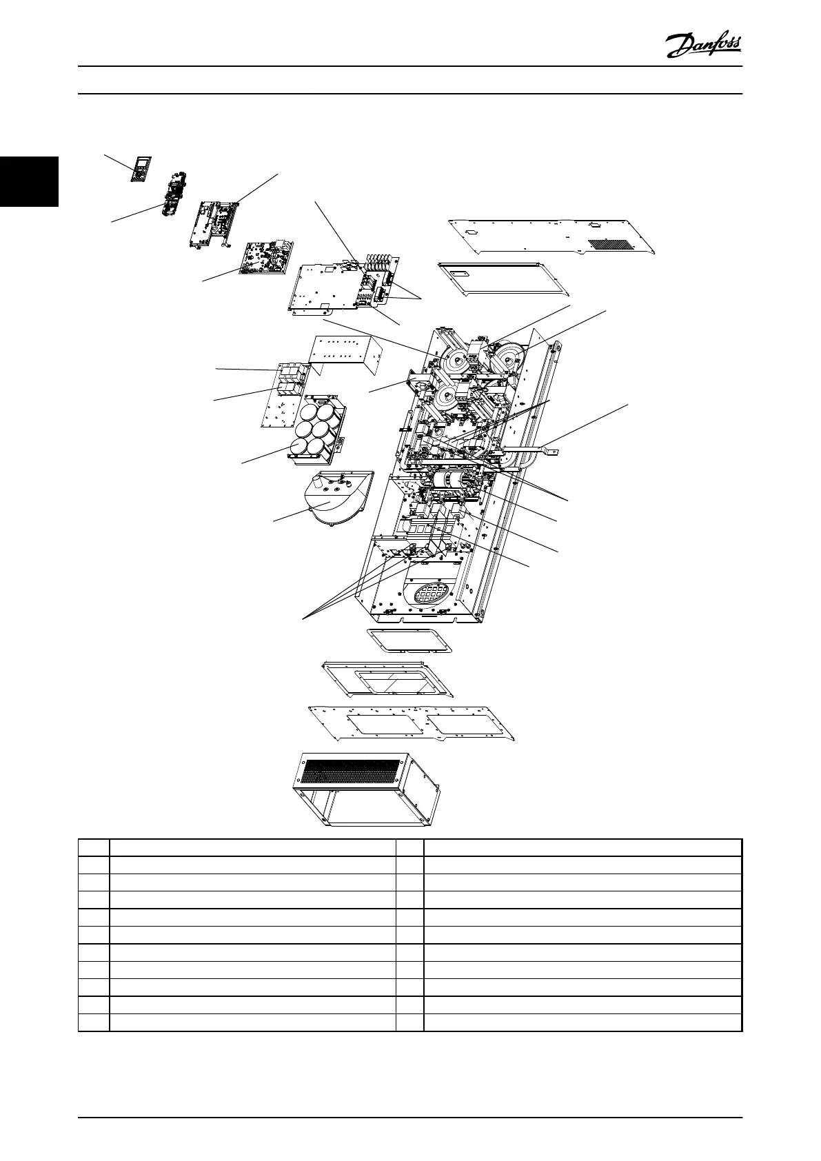
1 Local control panel (LCP) 13 Mains fuses
2 Active filter card (AFC) 14 Mains disconnect
3 Metal oxide varistor (MOV) 15 Mains terminals
4 Soft charge resistors 16 Heat sink fan
5 AC capacitors discharge board 17 DC capacitor bank
6 Mains contactor 18 Current transformer
7 LC inductor 19 RFI differential mode filter
8 AC capacitors 20 RFI common mode filter
9 Mains bus bars to drive input 21 HI inductor
10 IGBT fuses 22 Power card
11 RFI
Illustration 2.2 Frame Size D13 Filter Enclosure
Introduction
Operating Instructions
6 Danfoss A/S © Rev. 2014-07-29 All rights reserved. MG37A202
22

Table of Contents

Questions and Answers:

Question and Answer IconNeed help?

Do you have a question about the Danfoss VLT FC 302 and is the answer not in the manual?

Danfoss VLT FC 302 Specifications

General IconGeneral
Brake FunctionBuilt-in brake chopper in all units up to 22 kW
Output Voltage Range0-100% of input voltage
Power Range0.37 kW
Control ModesVVCplus, Flux, U/f
Protection FeaturesOvervoltage, undervoltage, overcurrent, short circuit, overtemperature, overload
Communication OptionsModbus RTU, BACnet, Ethernet/IP, Profinet, Profibus, CANopen, DeviceNet
Ambient Temperature Range-10°C to +50°C (derating above +40°C)
Enclosure RatingIP20, IP21, IP55
Cooling MethodAir-cooled
Input Voltage200-240V, 380-480V, 525-600V

Related product manuals