1
2
3
4
5
6
7
8
9
11
12
13 14 15 16 17
18
19
10
20
21
22
23
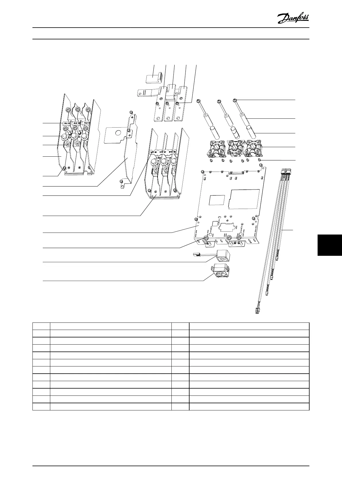
1 R/S/T terminal label 13 Insulator sleeve
2 Screw 14 U busbar
3 Nut 15 V busbar
4 Mains input terminal block 16 W busbar
5 Screw 17 Screw
6 EMC shield 18 Screw
7 U/V/W terminal label 19 Cylinder busbar
8 Motor terminal block 20 Nomex tube
9 Power terminal mounting plate 21 Current sensor
10 Nut 22 Thread-forming screw
11 Mixing fan 23 Wire harness (current sensor cables)
12 Mixing fan housing – –
Illustration 10.6 Power Terminals
D1h/D3h/D5h/D6h/J8 Drive Di... Service Guide
MG94A502 Danfoss A/S © 02/2019 All rights reserved. 139
10 10

 Loading...


