EasyManuals Logo

Danfoss VLT FC Series Service Guide

Danfoss VLT FC Series
370 pages
To Next Page IconTo Next Page
To Previous Page IconTo Previous Page
Page #30 background imageLoading...
Page #30 background image
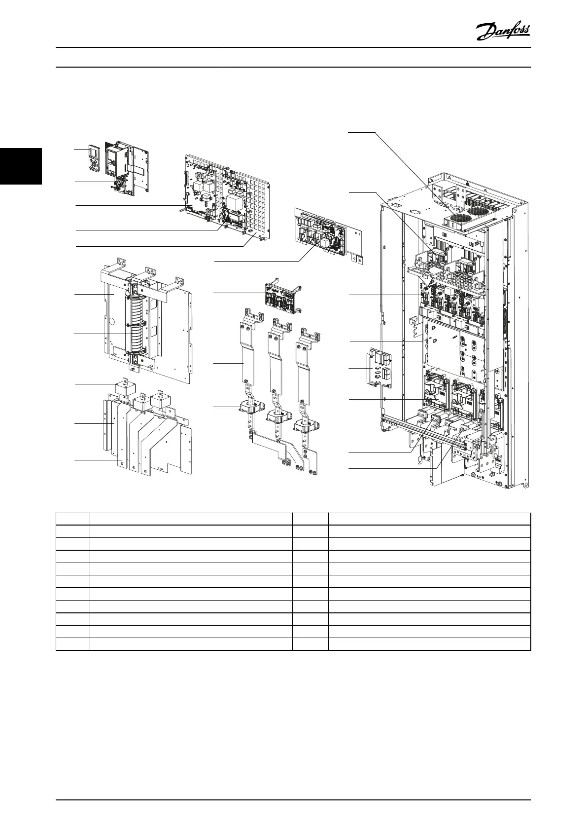
3.6.7 Exploded View of E-sized Unit
130BF879.10
7
1
2
6
8
9
10
3
4
5
11
12
13
14
15
16
17
19
20
21
22
18
1 LCP (Local control panel) 12 Gate drive card
2 Control card 13 Motor busbar assembly
3 Power card 14 Current sensors
4 Fan power card 15 Top fan
5 Power card mounting plate 16 SCR/diode modules
6 Upper input plate 17 IGBT modules
7 RFI lter (optional) 18 DC capacitor bank
8 AC fuses (optional) 19 Balance/high frequency card
9 Lower input plate 20 Heat sink fans
10 AC input busbars 21 Input terminals
11 Inrush card 22 Motor terminals
Illustration 3.8 Exploded View E3h Unit (E4h Unit is similar).
Product Overview
VLT
®
FC Series, D1h–D8h, Da2/Db2/Da4/Db4, E1h–E4h, J8/J9
28 Danfoss A/S © 02/2019 All rights reserved. MG94A502
33

Table of Contents

Other manuals for Danfoss VLT FC Series

Questions and Answers:

Question and Answer IconNeed help?

Do you have a question about the Danfoss VLT FC Series and is the answer not in the manual?

Danfoss VLT FC Series Specifications

General IconGeneral
CategoryDC Drives
SeriesVLT FC Series
Output Voltage0-100% of input voltage
Protection FeaturesOvervoltage, Undervoltage, Overcurrent, Short circuit, Overtemperature, Motor overload
Communication InterfacesCANopen, PROFIBUS, Ethernet
Cooling Methodliquid-cooled
Enclosure RatingIP20, IP21, IP55
Ambient Temperature-10°C to +40°C (14°F to 104°F) without derating

Related product manuals