11.2.18 DC Bus Rails
To remove or reinstall the DC bus rails with brake option, use the following steps. Refer to Illustration 11.11.
11.2.18.1 Without Optional Brake
Disassembly
1. Remove the power card mounting plate. Refer to
chapter 11.2.3 Power Card Mounting Plate.
2. Remove the power terminal mounting plate. Refer
to chapter 11.2.11 Power Terminal Mounting Plate.
3. Remove the 2 screws (T40) at the top end of the
DC bus rails, 1 per bus rail.
4. From the lower end of the DC bus rails, remove 4
nuts (10 mm), 2 per bus rail.
Reassembly
Tighten hardware according to chapter 14.1 Fastener Torque
Ratings.
1. Secure 2 screws (T40) at the top end of the DC
bus rails, 1 per bus rail.
2. Fasten 4 nuts (10 mm) at the lower end of the DC
bus rails, 2 per bus rail.
3. Replace the power terminal mounting plate. Refer
to chapter 11.2.11 Power Terminal Mounting Plate.
4. Replace the power card mounting plate. Refer to
chapter 11.2.3 Power Card Mounting Plate.
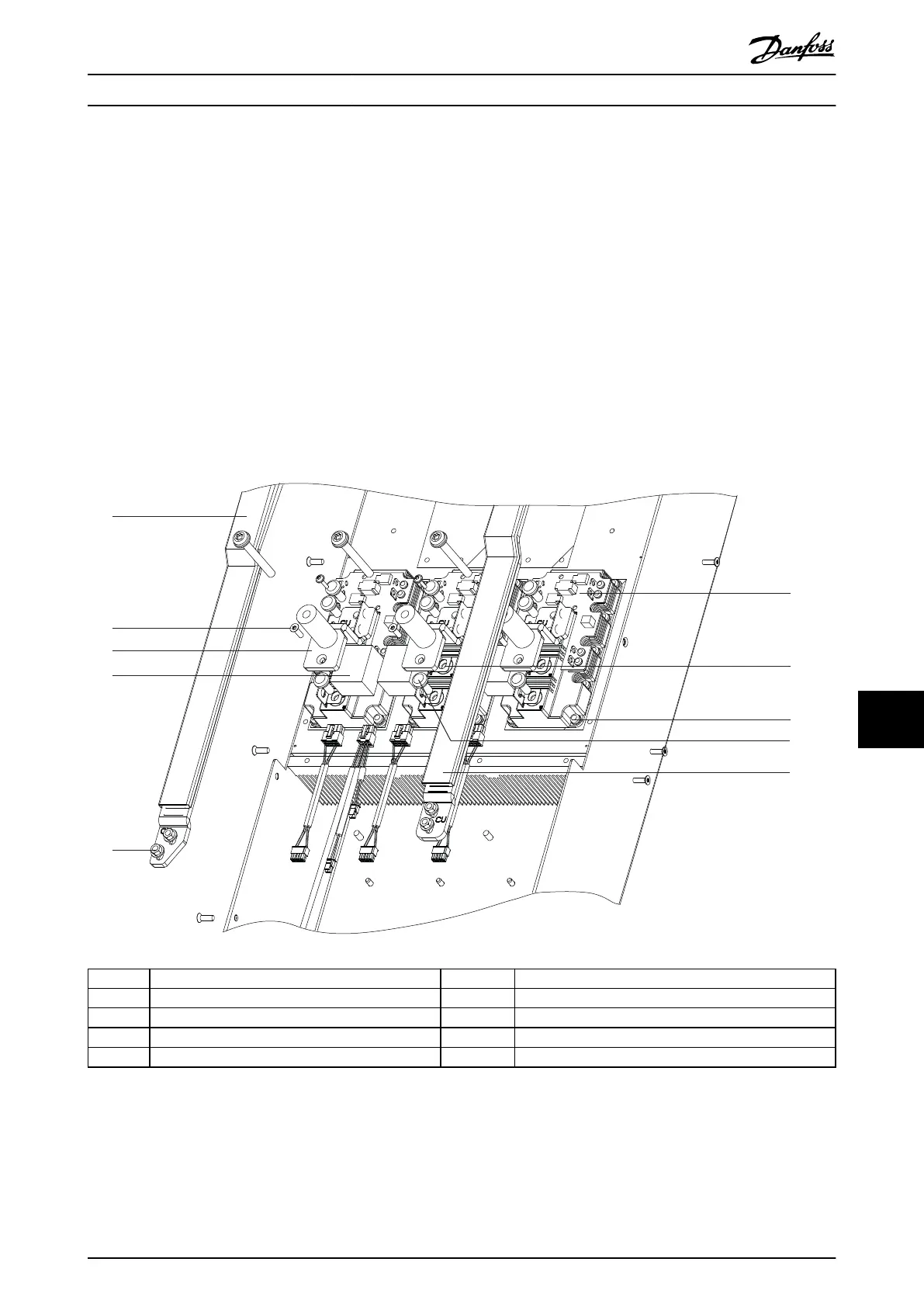
1 DC(+) bus rail 6 IGBT module
2 Screw (T20) 7 IGBT output busbar
3 IGBT output busbar 8 Screw (T40)
4 Snubber capacitor 9 Screw (T25)
5 Nut (8 mm) 10 DC(-) bus rail
Illustration 11.11 DC Bus Rails without Brake Option
D2h/D4h/D7h/D8h/J9 Unit Dis... Service Guide
MG94A502 Danfoss A/S © 02/2019 All rights reserved. 211
11 11

 Loading...


