powers the logic and interface circuitry. The SMPS is
supplied by the DC bus voltage. The drives can be
purchased with an optional secondary SMPS, which is
powered from a customer supplied 24 V DC source. This
secondary SMPS provides power to the logic circuitry with
mains input disconnected. It can keep units with communi-
cation options live on a network when the drive is not
powered from the mains.
The power card also supplies circuitry for controlling the
speed of the cooling fans.
Gate drive card
The gate drive signals from the control card to the output
transistors (IGBTs) are isolated and buered on the gate
drive card. In units that have the dynamic brake option,
the driver circuits for the brake transistors are also found
on this card.
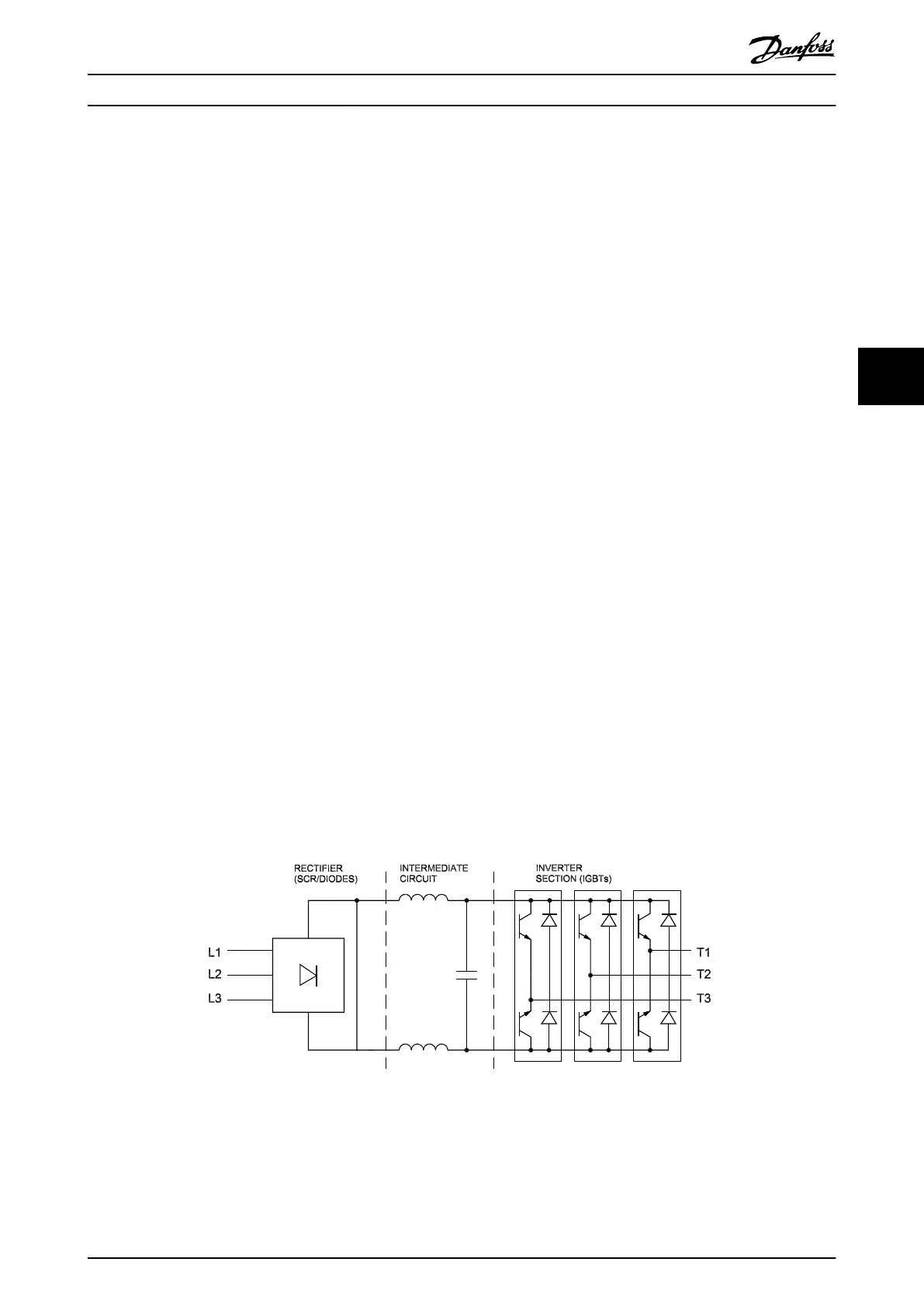
5.2.3 Power Section
The high voltage power section consists of the following
components:
•
AC input and motor output terminals
•
AC and DC busbars
•
Fuses
•
Wiring harness
•
Circuitry
- Soft charge and SCR/diode modules in
the rectier
- DC bus lter circuitry containing the DC
coils (intermediate or DC bus circuit)
- Output IGBT modules that make up the
inverter section.
•
Optional components
The inrush circuit controls the ring of the SCRs in the
rectier. When power is applied, the SCRs limit the
charging rate of the DC capacitors. Once the capacitors are
charged, the inrush circuit sequences the ring of the SCRs
to maintain the proper charge on the DC capacitors.
The DC bus circuitry regulates the pulsating DC voltage
created by the input AC supply.
The DC coil is a single unit with 2 coils wound on a
common core. One coil resides in the positive side of the
DC bus and the other in the negative. The coil aids in the
reduction of mains harmonics.
The DC bus capacitors are arranged into a capacitor bank
along with bleeder and balancing circuitry.
The inverter section is made up of insulated-gate bipolar
transistors, commonly referred to as IGBTs or switches. In
D-sized drives, there are 3 IGBT modules. In E-sized drives,
there are 6 IGBT modules. Each IGBT module contains
multiple IGBTs.
A Hall eect type current sensor is used on each phase of
the output to measure motor current. With Hall sensors,
the drive can monitor:
•
Average current.
•
Peak current.
•
Ground leakage current.
Illustration 5.3 Typical Power Section of an Individual Drive
Internal Drive Operation Service Guide
MG94A502 Danfoss A/S © 02/2019 All rights reserved. 45
5 5

 Loading...


