EasyManuals Logo

Danfoss VLT FC Series Service Guide

Danfoss VLT FC Series
370 pages
To Next Page IconTo Next Page
To Previous Page IconTo Previous Page
Page #26 background imageLoading...
Page #26 background image
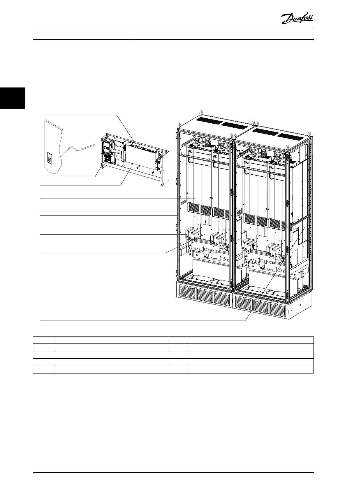
3.6.3 Exploded View of Multi-Drive System
This example of a 4-module system is composed of a control shelf and 4 VLT
®
Parallel Drive Modules in 2 side-by-side
enclosures. The control shelf attaches to the enclosure and holds the LCP and control card, as well as the MDCIC and control
terminals. Each module connects to the control shelf via a 44-pin ribbon cable. This example also includes an optional
busbar kit and optional cooling duct kits.
130BF896.10
2
3
5
4
6
1
7
9
8
1 MDCIC (behind cover plate) 6 Enclosure
2 LCP and cable 7 Busbar kit (optional)
3 Control card 8 EMC Shield
4 Control shelf 9 Cooling kit (optional)
5 Drive module
Illustration 3.4 Exploded View of 4-module System
Product Overview
VLT
®
FC Series, D1h–D8h, Da2/Db2/Da4/Db4, E1h–E4h, J8/J9
24 Danfoss A/S © 02/2019 All rights reserved. MG94A502
33

Table of Contents

Other manuals for Danfoss VLT FC Series

Questions and Answers:

Question and Answer IconNeed help?

Do you have a question about the Danfoss VLT FC Series and is the answer not in the manual?

Danfoss VLT FC Series Specifications

General IconGeneral
CategoryDC Drives
SeriesVLT FC Series
Output Voltage0-100% of input voltage
Protection FeaturesOvervoltage, Undervoltage, Overcurrent, Short circuit, Overtemperature, Motor overload
Communication InterfacesCANopen, PROFIBUS, Ethernet
Cooling Methodliquid-cooled
Enclosure RatingIP20, IP21, IP55
Ambient Temperature-10°C to +40°C (14°F to 104°F) without derating

Related product manuals