EasyManuals Logo

Danfoss VLT FC Series Service Guide

Danfoss VLT FC Series
370 pages
To Next Page IconTo Next Page
To Previous Page IconTo Previous Page
Page #195 background imageLoading...
Page #195 background image
1
10
8
6
5
4
7
3
2
130BF884.10
9
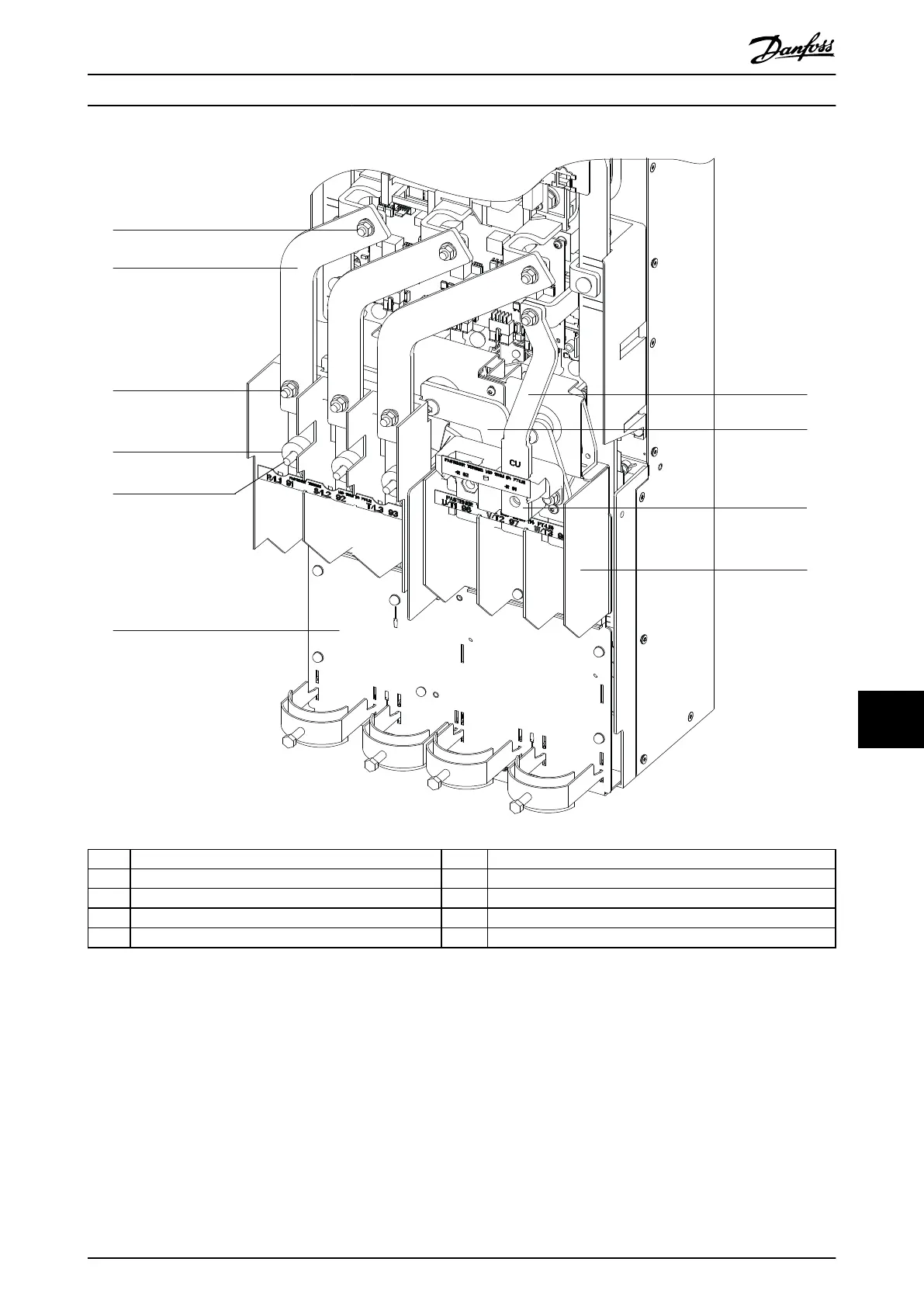
1 Top nut (13 mm) 6 Power terminal mounting plate
2 AC input busbar 7 Brake busbar (optional)
3 Bottom nut (13 mm) 8 U motor busbar
4 Fuse spacer 9 Brake terminal (optional)
5 Mains input terminal 10 Motor terminal block
Illustration 11.3 AC Input Busbars and Power Terminals
D2h/D4h/D7h/D8h/J9 Unit Dis... Service Guide
MG94A502 Danfoss A/S © 02/2019 All rights reserved. 193
11 11

Table of Contents

Other manuals for Danfoss VLT FC Series

Questions and Answers:

Question and Answer IconNeed help?

Do you have a question about the Danfoss VLT FC Series and is the answer not in the manual?

Danfoss VLT FC Series Specifications

General IconGeneral
CategoryDC Drives
SeriesVLT FC Series
Output Voltage0-100% of input voltage
Protection FeaturesOvervoltage, Undervoltage, Overcurrent, Short circuit, Overtemperature, Motor overload
Communication InterfacesCANopen, PROFIBUS, Ethernet
Cooling Methodliquid-cooled
Enclosure RatingIP20, IP21, IP55
Ambient Temperature-10°C to +40°C (14°F to 104°F) without derating

Related product manuals